Prostate segmentation and surface reconstruction
This page contains instructions on how to perform MRI prostate segmentation and surface reconstruction in MIPAV. The algorithm facilities the validation of multi-parametric MRI with histopathology slides from radical prostatectomy specimens and targeted biopsy specimens. It employs the technique that combines image processing and computer aided design to construct a high resolution 3D prostate surface from MRI images in three orthogonal views with non-isotropic voxel resolution.
The algorithm outline is shown below (TBD).
Contents
Image types
The algorithm could be applied to the following image types (TBD). In order to use the segmentation tool, the image dataset must contain 3 orthogonal images centered at prostate center, similar to the sample image dataset provided via this link.
Sample image dataset
The sample image dataset provided by NCI can be downloaded using this link (TBD). The data included into the data set are orthogonal MR images obtained from a 3.0 T whole-body MRI system (Achieva, Philips Healthcare).
T2-weighted MR images of the entire prostate were obtained in three orthogonal planes (sagittal, axial and coronal) using the following settings:
- Scan resolution of 0.2734x0.2734x3.0 cubic millimeters,
- Field of view - 140 mm,
- Image slice dimension 512x512.
The center of the prostate is the focal point for the MRI scan. To reduce the scan time, a lower refocusing pulse of 100 degrees was used for sagittal and coronal images, which alters the contrast on these images compared to the axial images.
Applying the algorithm
Applying the algorithm involves the following steps:
- Opening 3 orthogonal images and delineating VOIs (manually or using VOI from the the test image dataset);
- Prostate segmentation using Automatic B-Spline Registration algorithm;
- Prostate surface reconstruction;
- 3D Visualization and STL surface generation.
Opening images and delineating VOIs
Axial image
Open an axial image. Use File > Open image (A) from disk menu. If you are using the test image dataset provided, open the img_ax_83.xml file.
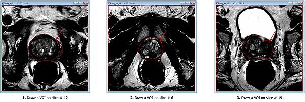
Draw 3 polygon/polyline VOIs. Use the Polygon/Polyline VOI tool ![]() from the MIPAV toolbar.
from the MIPAV toolbar.
For example, for the test image dataset provided:
- Draw the mid slice VOI first, on slice #12;
- Then draw the apex VOI, on slice #6;
- And finally, draw the last VOI on the base slice #19.
Smooth VOIs
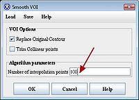
After delineating VOIs, we need to smooth each VOI. In order to do this, select each VOI and call the Smooth VOI dialog box available from the main MIPAV menu (VOI > Smooth VOI).
In the Smooth VOI dialog box, check the "Replace Original Contour" box, and set "Number of interpolation points" to 100. Click “OK”. Repeat for all 3 contours.
Sagittal and coronal images
Repeat the same process of delineating and smoothing VOIs for both sagittal and coronal images. for the test image dataset provided, the saggital image is img_sag_83.xml and the coronal image is img_cor_83.xml.
Example
In the image dataset provided, VOIs files are already available for all 3 types of images (axial, saggital and coronal). Under the image dataset directory, one can find 3 orthogonal images and corresponding VOIs:
| Orientation | Image file | VOI file |
|---|---|---|
| axial | img_ax_83.xml | voi_ax_83.xml |
| coronal | img_cor_83.xml | voi_cor_83.xml |
| saggital | img_sag_83.xml | voi_sag_83.xml |
The VOIs from the provided image dataset were drawn by clinical researchers, and verified by radiologist expert at NCI. For experimental purposes, we could recommend performing quick VOIs copying instead of manually drawing all three VOIs for all 3 image files.
How to copy VOIs
- Using MIPAV, open the same image twice, and open the VOIs file for the extra opened image. Let's name the first opened image the source image and the second opened image the extra image.
- From the MIPAV toolbar, use the Link Images tool
 to link the two images. Please, make sure to open the same image slice on each image, i.e. #12, before linking the images.
- Slide through the two images in parallel mode.
- Consequently open slices 6, 12, and 19 and make sure to copy 3 corresponding VOIs from the extra image to the source image.
- After finishing copying the three VOIs, unlink the two images.
- Close the extra image.
- Use smooth dialog to smooth the VOIs contours to 100 points.
- Repeat the same procedure for all three, axial, sagittal and coronal images.
Concurrent automatic MRI prostate segmentation
We will use the semi-automatic segmentation dialog to segment the MRI prostate. Before proceeding, please, make sure you open 3 orthogonal images with VOIs.

