Segmenting Images Using Contours and Masks: Using contours to segment a VOI
A VOI can consist of a single contour or several contoured structures that are assigned to a group. You can automatically, manually, or interactively draw contours on any image that is shown in the default view. You can modify the shape and size of a contour and trim anchor points.
Once contours are drawn and modified, you can copy them to other slices in the dataset or save them to a separate file for future use. The three overall tasks involved in using contours to segment a VOI are:
- Drawing contours ("Drawing contours")
- Modifying contours ("Modifying contours")
- Grouping and ordering contours ("Grouping and ordering contours")
Contents
Drawing contours
You can draw contours using three different methods: manual, interactive, or automatic. With the manual method, you use the mouse to draw a contour. This method provides the greatest amount of freedom: you can choose one of MIPAV's predefined shapes or create a freehand shape. However, the manual method can be time consuming, particularly if the structure to be contoured is intricate. With the interactive method, you must also manually contour the structure. However, in this case the manually drawn contour need not be precise because you then apply an algorithm that generates a new contour based on both the manually drawn contour and the structure. With the automatic method, MIPAV generates contours as you move the mouse over different structures. The automatic method is generally accurate and quick; however, it does not provide the freedom of the manual method.
Recommendation: If you are unsure about which contour method to use, it is recommended that you try the automatic method first.
Contouring structures automatically
In this method, you move the mouse pointer over a structure. MIPAV first analyzes the intensity values and then contours what it perceives to the contour boundary.
Complete the following steps:
1 Select VOI > New VOI > Levelset in the MIPAV window.
2 Move the mouse pointer to the image.
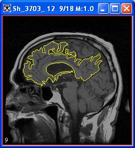
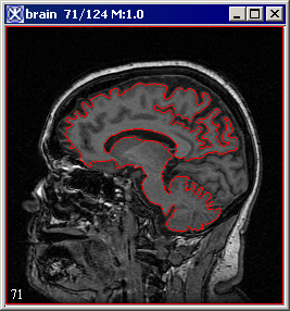
The pointer changes to the cross-hair shape. As you move the pointer, MIPAV determines the level of intensity of the pixel under the cross-hair pointer and uses the results from the Levelset algorithm to determine the probable boundary of the structure. Having determined the probable boundary, MIPAV generates a contour (Figure 1). Continue to move the pointer until the structure you wish to outline is contoured.
3 Click the contour to apply it to the structure. See Figure 1.
| You can now do the following: Draw an additional contour |
Contouring structures manually
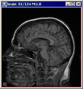
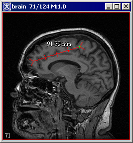
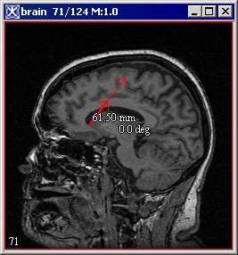
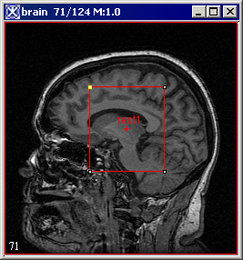
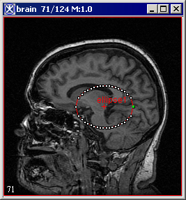
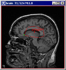
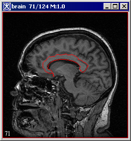
You can contour structures in images by selecting one of MIPAV's predefined shapes, such as a point, straight line, 2D or 3D rectangle, 2D ellipse, interslice VOI, etc. Alternatively, you can use the polygon and polyline tools to draw freehand shapes. For more information about VOIs available in MIPAV, refer to Figure 2.
|
|
|
|
|
|
|
|
This section explains how to draw the following:
Point VOIs
VOIs with a straight line
2D rectangular VOIs
3D rectangular VOIs
Ellipsoidal VOIs
Polyline (segmented line) and closed polygon VOIs
Tip Before you begin, decide whether you want to draw more than one of the same contour in succession. If you do, hold down the Shift key as you select the contour button and draw the contours.
To draw point VOIs
![]() - Draw Point VOI
- Draw Point VOI
1 Click the Draw Point VOI button, in the MIPAV window.
2 Move the pointer to the image.
3 Click the area where you want the point to appear. A numbered point appears on the image.
For some algorithms, the sequence in which you draw the points is important (refer to Volume 2 of the User's Guide.
To create VOIs with a straight line![]() - Draw Line VOI
- Draw Line VOI
1 Click the Draw line VOI icon.
2 Click the area on the image where you want the line to begin.
3 Drag the pointer to the place where you want the line to end. As you drag the pointer, the line lengthens.
4 Release the mouse button. The line VOI appears on the image in red.
To create 2D rectangular VOIs
![]() - Draw Rectangular VOI
- Draw Rectangular VOI
1 Click the Draw Rectangle VOI icon.
2 Click the area on the image where you want a corner of the rectangle to appear.
3 Drag the pointer. As you drag the pointer, the rectangle changes in size.
4 Release the mouse button when the rectangle is the desired size.
When you create a 2D rectangular VOI, the rectangles appear on only one slice in the dataset.
To create 3D rectangular VOIs
![]() - Draw 3D Rectangular VOI
- Draw 3D Rectangular VOI
1 Click the 3D rectangular VOI icon.
2 Click the area on the image where you want a corner of the rectangle to appear.
3 Drag the pointer. As you drag the pointer, the rectangle changes in size.
4 Release the mouse button when the rectangle is the desired size.
Unlike 2D rectangular VOIs, 3D rectangular VOIs appear on all slices in the dataset.
<
To create ellipsoidal VOIs
![]() - Draw Ellipsoid VOI
- Draw Ellipsoid VOI
1 Click the Draw Ellipse VOI icon.
2 Click the area of the image where you want an edge of the ellipse to appear.
3 Drag the pointer. As you drag the pointer, the ellipse changes in size.
4 Release the mouse button when the ellipse is the desired size (Figure 2).
To create polyline (segmented line) VOIs or closed polygon VOIs
![]() - Draw Polygon/Polyline VOI
- Draw Polygon/Polyline VOI
1 Click the Draw Polygon/Polyline VOI icon.
2 Click the area of the image where the polyline VOI should begin.
3 Decide whether to draw either a straight or freehand line segment. Do one of the following:
- To draw a straight line segment
Make sure that you have released the mouse button. Move the pointer to the place where you want the segment to end. A straight line, which extends from the starting place to your pointer tip, appears. Click the mouse button to anchor the line segment.
- To draw a freehand line segment
Drag the mouse button and move the pointer to the place on the image where you want the segment to end. A line, which matches your mouse movements, extends from the starting place to your pointer tip. Click the mouse button to anchor the line segment.
4 Repeat drawing straight line segments or freehand lines until you finish drawing all of the segments needed to contour the structure.
5 Decide whether to create a polyline VOI or a closed polygon VOI:
- Polyline VOI: Go to the next step.
- Closed polygon VOI:
Click the first anchor point to connect the last line segment to the first, thus forming a closed polygon. Then go to the next step.
6 Click the Default icon, to return the pointer to the default mode.
7 Double-click the mouse button to complete the polyline VOI.
Tip: Depending on which is more comfortable, you can switch between drawing straight line segments or drawing freehand lines at any time.
Tip: To draw multiple VOI, hold Shift while pressing the corresponding VOI icon.
Contouring structures interactively
In the interactive method, you first manually draw a contour that provides a general indication of the location and shape of the structure. You then select an algorithm that analyzes the manually drawn contour and generates a new one that more closely outlines the structure.
To use the interactive method to contour structures, complete the following steps:
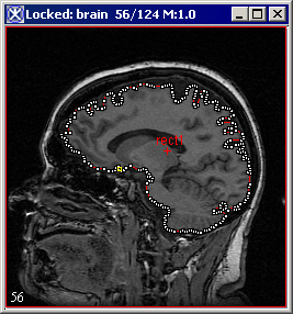
1 Draw a contour using one of the manual methods detailed in "Contouring structures manually" . The contour need not be precise, but it should indicate the general location and shape of the structure you want to delineate.
2 Select the contour. White anchor points appear on the contour outline.
<
3 Select one of the following in the MIPAV window:
VOI > Evolve Boundary 2D > Active Contour.
This algorithm determines the structure's boundary more quickly than the 2D Spline Active Contour algorithm. It is also more sensitive to noise present in the image. MIPAV applies a gradient magnitude filter to determine the structure's boundary. When complete, the MIPAV-generated contour appears around the structure.
VOI > Evolve Boundary 2D > Active GVF.
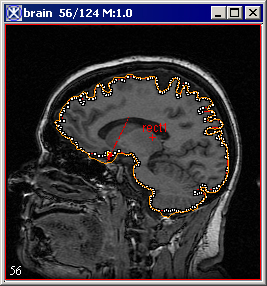
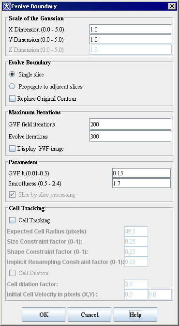
The Evolve Boundary dialog box uses a special type of active contours, or snakes to find the object boundaries. GVF or the gradient vector flow snake, which is used to calculate VOI boundaries, begins with the calculation of a GVF field of forces by applying generalized diffusion equations to both components of the gradient of an image edge map. Here, GVF fields, are dense vector fields derived from images by minimizing a certain energy functional in a variational framework. The minimization is achieved by solving a pair of decoupled linear partial differential equations that diffuses the gradient vectors of a gray-level or binary edge map computed from the image. See also Figure 3.
VOI > Evolve Boundary 2D > Spline active contour. This algorithm determines the structure's boundary less quickly than the Active Contour algorithm, however it is less sensitive to noise. This algorithm fits a spline to the data. When complete, the MIPAV-generated contour appears around the structure.
VOI > Evolve Boundary 2D > Spline GVF. This is the combination of the GVF force with the B-spline snake. B-spline snakes have several characteristics which make them well suitable for describing VOI boundary as well as snake evolution: the B-spline implicitly incorporates contour smoothness and avoids the ad hoc< tension and rigidity parameters of the traditional GVF snake and also fewer sample points are required to implement contour evolution for the B-spline.
A
|
B
|
Evolve Boundary dialog box options
|
Scale of the Gaussian
|
A large Gaussian scale slows the snake and causes it to conform to large scale structure. A small Gaussian scale causes the snake to conform to the small scale structure, which is therefore more sensitive to noise.
|
|
|
Evolve Boundary
|
Single Slice - applies the algorithm only on a current image slice. Propagate to adjacent slices - propagates boundaries to adjacent slices. Note that the algorithm used for 3D images version is a 2.5D dimensional algorithm where the resultant contour in a slice is projected into the adjacent slice and is used as an initialization to the evolution in the new slice. Replace original contour - if checked, replaces the original VOI.
| |
|
Maximum Iterations
|
GVF field iterations - enter a desired number of GVF iterations here. Evolve iterations - enter a max number of iterations needed to generate a new VOI boundary. Display GVF image; if this box is checked, the GVF image appears in a new image frame.
| |
|
Parameters
|
GVFk is a positive constant controlling the smoothness of the resulting VOI. Smoothness corresponds to the balance between internal and external forces. The internal force constrains the snake to be smooth while the external guides the snake to seek desirable image properties, such as edges. Slice by slice processing - if checked, this activates evolving boundary slice by slice.
| |
|
Cell Tracking
|
Cell Tracking - if checked, this box activates the cell tracking algorithm; Expected Cell Radius (in pixels) - a user-defined cell radius Size Constraint and Shape Constraint factors are contributed towards the shape and size of the snake in order to make it circular with a user-defined cell radius. Implicit Resampling Constraint factor minimizes the number of points along the snake curve, thus they maintain an equal distance. Cell Dilation - if checked, allows dilation Cell dilation factor is multiple of the cell radius Initial Cell Velocity in pixels (X,Y)
| |
|
OK
|
Applies the parameters that you specified.
| |
|
Close
|
Disregards any changes that you made in this dialog box and closes the dialog box.
| |
|
Help
|
Displays online help for this dialog box.
| |
