Select Algorithms and Brain Tools for Talairach Transform
From MIPAV
10 Select Algorithms > Brain tools> Talairach transform.
</font></div>
The Talairach Transform dialog box ([TechGuide_MappingBrainsTalairach.html#1356882 Figure 24]) opens.
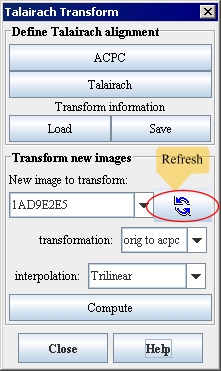
Figure 24. Talairach Transform dialog boxÂ
|
ACPC
|
Transforms the original image of a brain into an AC-PC aligned image in which the anterior and posterior commissures in the brain are set on a horizontal line. When you click this button, the Create AC-PC Image dialog box opens.
|
{| align="center"
|
|
|-
|
Talairach
| rowspan="1" colspan="2" |
Transforms the AC-PC image of the brain into a Talairach-aligned image. When you click this button, the Create Talairach Image dialog box opens.
|-
|
Load
| rowspan="1" colspan="2" |
Loads a previously saved AC-PC or Talairach transform into the original image. When you click this button, either the Load Talairach Transform File or the Load AC-PC Transform dialog box opens.
|-
|
Save
| rowspan="1" colspan="2" |
Saves the AC-PC or the Talairach transform to a .txt file. When you click this button, the Save AC-PC Transform File or Save Talairach Transform dialog box opens.
|-
|
New image to transform
| rowspan="1" colspan="2" |
Displays a list of the original image and, if you click Refresh, any AC-PC or Talairach images that are currently open.
|-
|
Refresh
| rowspan="1" colspan="2" |
Refreshes the list of images in the New image to transform list to reflect any
AC-PC or Talairach images that are currently open.
|-
| rowspan="6" colspan="1" |
Transformation
|
Orig to AC-PC
|
Transforms the original image to the AC-PC image. You choose this item to copy information from the original image to the AC-PC image.
|-
|
Orig to Tlrc
|
Transforms the original image to the Talairach image. You choose this item to copy information from the original image to the Talairach image.
|-
|
ACPC to Tlrc
|
Transforms the AC-PC image to the Talairach image. You choose this item to copy information from the AC-PC image to the Talairach image.
|-
|
Tlrc to AC-PC
|
Transforms the Talairach image to the AC-PC image. You choose this item to copy information from the Talairach image to the AC-PC image.
|-
|
Tlrc to orig
|
Transforms the Talairach image to the original image. You choose this item to copy information from the Talairach image to the original image.
|-
|
AC-PC to orig
|
Transforms the AC-PC image to the original image. You choose this item to copy information from the AC-PC image to the original image.
|-
|
Interpolation
| rowspan="1" colspan="2" |
Indicates the method of interpolation to use when creating AC-PC or Talairach images. The default interpolation method is trilinear. However, you can choose any of the following interpolation methods, which are listed in order of complexity and amount of time required:
Nearest neighbor
Trilinear
Bspline 3rd order
Bspline 4th order
Cubic Lagrangian
Quintic Lagrangian
Heptic Lagrangian
Windowed sinc
See also: "Interpolation methods used in MIPAV" .
|-
|
Compute
| rowspan="1" colspan="2" |
Transforms the new image according to the transformation chosen in Transformation. When you click Compute, the Talairach plugin stores the AC-PC and Talairach transform information in the image headers. To view this information, select the image and then select Image > Attributes > View header.
|-
|
Close
| rowspan="1" colspan="2" |
Closes the Talairach Transform dialog box and quits the Talairach plugin.
|-
|
Help
| rowspan="1" colspan="2" |
Displays online help for this dialog box.
|}
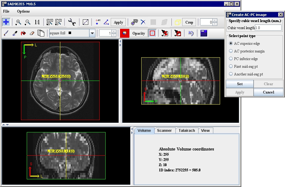
11 Click AC-PC at the top of the Talairach Transform dialog box. The following occurs:
The image appears in a triplanar view ([TechGuide_MappingBrainsTalairach.html#1221273 Figure 25]).
The Create AC-PC Image dialog box ([TechGuide_MappingBrainsTalairach.html#1221273 Figure 25]) opens on top of the triplanar view.
Note: If the image appears squeezed or otherwise out of alignment, you need to make sure that the resolutions on the Resolutions page of the Image Attributes window are correct.
The Create AC-PC Image dialog box ([TechGuide_MappingBrainsTalairach.html#1221273 Figure 25]) lists five landmark points that you need to locate and mark in the image. [TechGuide_MappingBrainsTalairach.html#1221278 Table 5] lists these points and their approximate location in the image. [TechGuide_MappingBrainsTalairach.html#1221367 "Guide to Finding Landmark Points" on page 19] illustrates the location of the points.
Tip: To create the AC-PC image, you may need to magnify the image a couple of times, particularly for locating the AC superior edge, AC posterior margin, and PC inferior edge (refer to [TechGuide_MappingBrainsTalairach.html#1298422 Figure 28 on page 22]).
Figure 25. The Create AC-PC Image dialog box on top of the triplanar view of the image
|
{| align="center"
|
|
|}
Table 5. Landmark points needed to perform AC-PC alignment
|
Symbol used on image
|
Landmark points
|
Location in image
|
|
Abbreviation
|
Color
|
|
ACS
|
Red
|
AC superior edge
|
Top middle of anterior commisure
|
|
ACP
|
Orange
|
AC posterior margin
|
Rear middle of anterior commissure
|
|
PC
|
Yellow
|
PC interior edge
|
Bottom middle of posterior commisure
|
|
MS1
|
Aqua
|
First midsagittal point
|
Some point in the midsagittal plane
|
|
MS2
|
Yellow
|
Second midsagittal point
|
Another point in the midsagittal plane
|
|
Guide to Finding Landmark Points
|
|
First Goal
Mark the top middle and rear middle of the anterior commisure.
In the sagittal image-Look for the anterior commisure at the bottom level of the corpus collosum, below the fornix.
In the coronal view-Look for the "mustache."
In the axial view-Look for the interhemispheric connection.
Second Goal
Mark the inferior edge of the posterior commissure.
Unfortunately, the posterior commissure doesn't show up well at 1-mm resolution. However, it is always at the top of the cerebral aqueduct, which usually shows up well.
|
If you can't see the posterior commissure, find the midsagittal location just at the top of the cerebral aqueduct and mark it as the PC inferior edge.
Final Goal
Mark two midsagittal points (SG1 and SG2), which are above the corpus callosum.
The two planes of AC-SC-SG1 and AC-PC-SG2 must be no more than 2 degrees apart. In practice, good candidates for SG1 and SG2 are often far from AC and PC and close to each other.
The following diagram shows where the points are located. An image in a triplanar view in which the image was magnified twice appears in [TechGuide_MappingBrainsTalairach.html#1298422 Figure 28 on page 22].
To find the landmark points, it is extremely helpful to have a high-quality image of the anterior and posterior commissures.
|
|
Â
Â
Â
Â
Â
{| align="center"
|
File:ExampleACPCalignment.gif
|
Figure 26. Landmark points used to perform AC-PC alignment
|}
12 Set the scale of the image in Cubic voxel length. Make sure this scale matches the entries in [TechGuide_MappingBrainsTalairach.html#1221168 step 4].
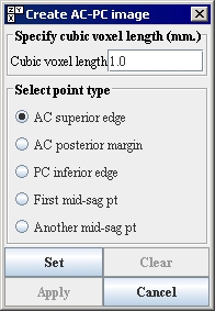
13 Select AC superior edge in the Create AC-PC Image dialog box ([TechGuide_MappingBrainsTalairach.html#1221436 Figure 27]).
14 Go to the triplanar image and locate the AC superior edge on the sagittal view of the image. Place the crosshair marker directly over the top middle of the anterior commisure.
15 Click Set on the Create AC-PC Image dialog box ([TechGuide_MappingBrainsTalairach.html#1221436 Figure 27]). A red marker labeled ACS appears on the point you indicated.
Figure 27. Create AC-PC Image dialog box
|
{| align="center"
|
|
|}
16 Select, locate, and set each of the remaining landmark points consecutively in the Create AC-PC Image dialog box. Refer to [TechGuide_MappingBrainsTalairach.html#1221278 Table 5 on page 19], [TechGuide_MappingBrainsTalairach.html#1221367 "Guide to Finding Landmark Points" on page 19], and [TechGuide_MappingBrainsTalairach.html#1298422 Figure 28 on page 22] for directions on how to locate the individual points.
Figure 28. Finding landmark points: (A) AC superior edge in original image, (B) AC superior edge in magnified image, (C) PC inferior edge in original image, and (D) PC inferior edge in magnified imageÂ
|
{| align="center"
|
File:ExampleTalairachTransformation PilouAC.gif
|
|-
|
|}
Note: If you need to erase a landmark point that you've already set, select the point in the image. Return to the Create AC-PC Image dialog box and select the radio button for the point you want to delete. For example, to delete the AC posterior margin, select that radio button. Then click Clear (the Clear button only becomes available when you've completed the preceding instructions correctly).
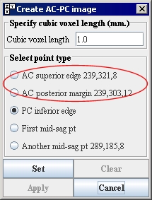
17 Return to the Create AC-PC Image dialog box ([TechGuide_MappingBrainsTalairach.html#1221505 Figure 29]) when all landmark points are marked, and click Apply.
Tip: The Apply button only becomes available when all of the landmark points are correctly selected and set. A point is correctly set when the settings you chose appear to the right of each point ([TechGuide_MappingBrainsTalairach.html#1221505 Figure 29]).
A progress message appears, and then the image produced from the settings you specified appears in a new image window. The result is an AC-PC aligned image ([TechGuide_MappingBrainsTalairach.html#1221529 Figure 31]).
Figure 29. Create AC-PC Image dialog box with settings for each of the landmark points. After the landmark point is set, it's coordinates appear in the dialog box
|
{| align="center"
|
|
|}
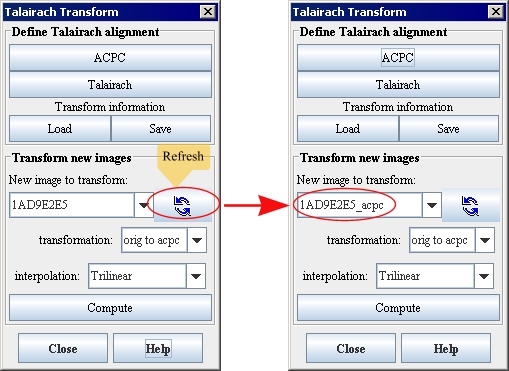
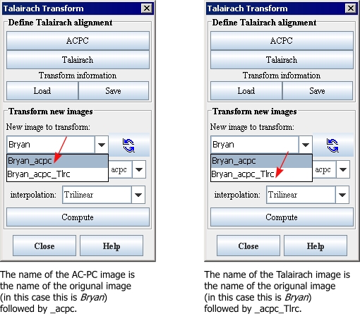
18 Refresh the list of images in New image to transform. The transformed image, whose title is the name of the original image followed by _acpc, appears in the list ([TechGuide_MappingBrainsTalairach.html#1292608 Figure 30]).
Figure 30. The New image to transform box after clicking the Refresh icon
|
{| align="center"
|
|
|}
Note: The slice of the AC-PC image that displays may differ from the slice shown in the original image. By default, the AC-PC image appears at its center slice.
You may now want to save the AC-PC transform. If somehow you are interrupted in the procedure of transforming a brain image into Talairach space, saving the transform prevents your having to perform AC-PC alignment again.
Figure 31. A comparison of (a) the original brain with marked landmark points and (B) the image after AC-PC alignment showing, by default, the center slice and (C) image after AC-PC alignment showing same slice as the original image
|
{| align="center"
|
File:ExampleTalairachPointsMarkedOriginalBrainACPCBrain.gif
|
|}
To save the AC-PC transform (recommended)
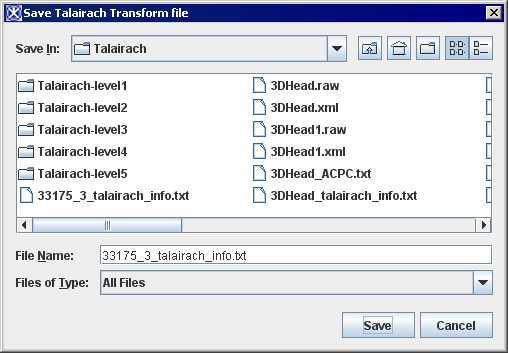
1 Click Save in the Talairach Transform dialog box. The Save Talairach Transform File dialog box ([TechGuide_MappingBrainsTalairach.html#1221547 Figure 32]) opens.
2 Navigate to the directory in which you want to save the transform.
3 Type the file name for the transform and the extension .txt.
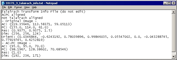
Note: The AC-PC transform file is a text document that can be read with any text editor, such as Microsoft Notepad.
4 Click Save. MIPAV saves the AC-PC transform to the folder you specified.
Figure 32. Save Talairach Transform dialog box
|
{| align="center"
|
|
|}
5 Type the file name for the transform and the extension .txt.
Note: The AC-PC transform file is a text document that can be read with any text editor, such as Microsoft Notepad.
6 Click Save. MIPAV saves the AC-PC transform to the folder you specified.
Figure 33. An example of an AC-PC transform file, which is a text file
|
{| align="center"
|
|
|}
To resolve errors
An error may occur if there is a 2-percent angular difference between the planes defined by AC-PC-MS1 and AC-PC-MS2. To resolve it, the ideal way is to align perfectly the MS1 and MS2 points on the midsagittal plane: using well-defined planes (choosing MS1 and MS2 far from the AC-PC line, one rather on the front and one on the back of the brain). If that fails, there is still the much less reliable method to have both MS points close to each other, so they define about the same plane.
To view the AC-PC settings for the AC-PC transformed image
1 Select the AC-PC transformed image that you just created.
2 Select Image > Attributes > Edit Attributes. The Image Attributes dialog box opens.
3 Click Talairach. The Talairach page appears.
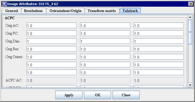
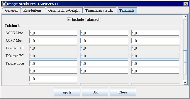
4 Enlarge the Image Attributes dialog box ([TechGuide_MappingBrainsTalairach.html#1269303 Figure 34]) to show all of the fields in the dialog box.
Now that you have performed the AC-PC transformation on the image, the settings appear in the AC-PC group. However, because you have not yet performed the Talairach transformation on the image, the settings for the fields in the Talairach group still remain "1.0".
5 Click Close. The Image Attributes dialog box closes.
Figure 34. Enlarged Image Attributes dialog box showing AC-PC settings but no Talairach settings
|
{| align="center"
|
|
|}
To load a previously saved AC-PC transform
1 Open the original image of the brain on which you performed AC-PC alignment.
2 Select Plug-Ins > Algorithms > TalairachTransform. The Talairach Transform dialog box opens.
3 Select the name of the original image in New image to transform.
4 Select acpc to orig. in Transformation.
5 Click Load. The Load Talairach Transform File dialog box opens.
6 Navigate to the directory in which you saved the AC-PC .txt file and select the file.
7 Click Open. A message appears on the Data page in the Outlook window saying that "transform data loaded from <path>."
8 Click Compute. A progress message appears, and then the image produced from the loaded AC-PC transform appears in a new image window. The result is an AC-PC aligned image.
Performing Talairach alignment
The AC-PC image that was generated now needs to be aligned in the Talairach coordinate system. Talairach alignment consists in scaling the brain to match its boundaries with those of the Talairach atlas. It is a 12 degrees of freedom, piece wise linear transform. It brings the AC, PC, and anterior, posterior, left, right, inferior, and superior boundaries of the brain to normalized positions ([TechGuide_MappingBrainsTalairach.html#1221594 Figure 35 on page 30]).
After the AC-PC image is generated, it is necessary to find the six most anterior, posterior, left, right, inferior, and superior points, or, alternatively, the bounding box enclosing the brain. These points, along with the AC-PC landmark points, define a set of 12 boxes. In each box independently, the image is scaled along the three dimensions of the Talairach coordinates. Continuity is guaranteed since the boxes share common faces.
Talairach alignment is nonlinear as it scales differently the 12 boxes. Any direct measurement in this coordinate system is irrelevant: voxels have a different resolution in different boxes. For this reason, it is important to have the ability to bring back any Talairach-aligned image into the original image or the AC-PC aligned coordinates.
|}
To perform Talairach alignment
1 Select the AC-PC image in New image to transform box in the Talairach Transform dialog box ([TechGuide_MappingBrainsTalairach.html#1295708 Figure 36]).
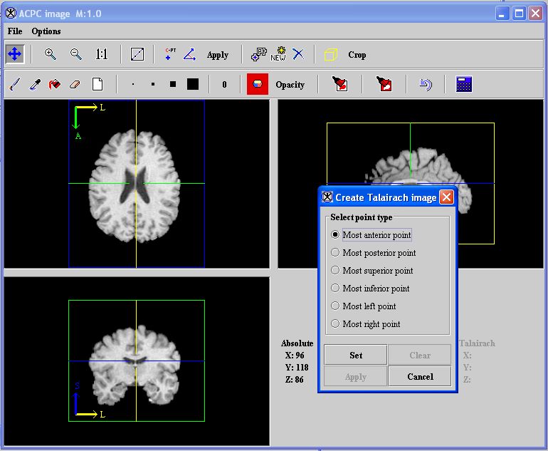
2 Select Talairach. The Create Talairach Image dialog box ([TechGuide_MappingBrainsTalairach.html#1221664 Figure 37 on page 32]) appears on top of a triplanar view of the AC-PC image.
Tip: The goal at this point is to mark the limits of the brain: most anterior, most posterior, most superior, most inferior, most left, and most right points. The exact location of the points is not important as long as they bound the cerebrum.
3 Select Most anterior point in the Create Talairach Image dialog box.
4 Go to the triplanar view of the image. Select the point that is the most anterior point in the image. The important information is the position of the green line.
5 Click Set in the Create Talairach Image dialog box.
6 Repeat this procedure for the remaining points. When you finish setting the points, the Apply button becomes available.
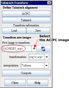
Figure 36. New image to transform box in the Talairach Transform dialog box
|
{| align="center"
|
|
Â
Â
|}
7 Click Apply. A status message appears during processing. When processing is complete, the Talairach aligned image ([TechGuide_MappingBrainsTalairach.html#1221675 Figure 38]) appears.
8 Click the Refresh button to refresh the list of images in New image to transform. The transformed image, whose title is the name of the original image followed by _acpc_Tlrc, appears in the list ([TechGuide_MappingBrainsTalairach.html#1296015 Figure 39 on page 33]).
At this point, you may want to save the Talairach transform. Doing so eliminates the need to repeat the Talairach process for this dataset. If interruptions at this point prevent you from completing tasks 2 through 6, saving the transform allows you to resume where you left off.
The transform is saved as a text (.txt) file.
Note: You can use the Talairach transformation to bring other co-registered images into Talairach space and to send atlas information into the original image space.
Figure 37. The Create Talairach Image dialog box on top of the triplanar view of the AC-PC image
|
{| align="center"
|
|
|}
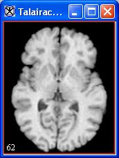
Figure 38. Talairach-aligned image
|
{| align="center"
|
|
|}
Figure 39. Labeling of AC-PC images and Talairach images
|
Â
Â
{| align="center"
|
|
|}
To save the Talairach transform (recommended)
1 Select the Talairach-aligned image that was generated.
2 Click Save in the Talairach Transform dialog box. The Save Talairach Transform File dialog box ([TechGuide_MappingBrainsTalairach.html#1221547 Figure 32]) opens.
3 Navigate to the directory in which you want to save the transform.
4 Type the file name for the transform and the extension .txt.
5 Click Save. The Talairach transform is saved in the folder you specified.
Note: The Talairach transform file is a text document that can be read with any text editor, such as Microsoft Notepad.
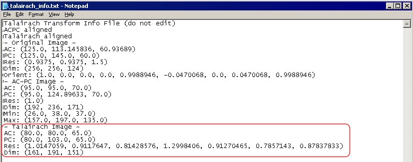
Figure 40. An example of a Talairach transform file, which is a text file
|
{| align="center"
|
|
|}
To view the Talairach settings for the Talairach-transformed image
1 Select the Talairach-transformed image.
2 Select Image > Attributes > Edit Attributes in the MIPAV window. The Image Attributes dialog box opens.
3 Click Talairach. The Talairach page appears.
4 Enlarge the Image Attributes dialog box ([TechGuide_MappingBrainsTalairach.html#1269706 Figure 41]) to show all of the fields in the dialog box.
The settings in the Talairach group should now reflect the settings for the Talairach-transformed image. The Talairach page should also still show the settings for the AC-PC transformed image.
5 Click Close. The Image Attributes dialog box closes.
Figure 41. Image Attributes dialog box showing both the AC-PC settings and the Talairach settings
|
{| align="center"
|
|
|}
Task 2, Applying Talairach VOIs


