Segmenting Images Using Contours and Masks: Using contours to segment a VOI
From MIPAV
Using contours to segment a VOI
A VOI can consist of a single contour or several contoured structures that are assigned to a group. You can automatically, manually, or interactively draw contours on any image that is shown in the default view. You can modify the shape and size of a contour and trim anchor points.
Once contours are drawn and modified, you can copy them to other slices in the dataset or save them to a separate file for future use. The three overall tasks involved in using contours to segment a VOI are:
Drawing contours ([MIPAV_Segmentation.html#998348 "Drawing contours" on page 259])
Modifying contours ([MIPAV_Segmentation.html#1613292 "Modifying contours" on page 268])
Grouping and ordering contours ([MIPAV_Segmentation.html#1023231 "Grouping and ordering contours" on page 273])
Drawing contours
You can draw contours using three different methods: manual, interactive, or automatic. With the manual method, you use the mouse to draw a contour. This method provides the greatest amount of freedom: you can choose one of MIPAV's predefined shapes or create a freehand shape. However, the manual method can be time consuming, particularly if the structure to be contoured is intricate. With the interactive method, you must also manually contour the structure. However, in this case the manually drawn contour need not be precise because you then apply an algorithm that generates a new contour based on both the manually drawn contour and the structure. With the automatic method, MIPAV generates contours as you move the mouse over different structures. The automatic method is generally accurate and quick; however, it does not provide the freedom of the manual method.
Recommendation. If you are unsure about which contour method to use, it is recommended that you try the automatic method first.
Contouring structures automatically
In this method, you move the mouse pointer over a structure. MIPAV first analyzes the intensity values and then contours what it perceives to the contour boundary.
Complete the following steps:
1 Select VOI > New VOI > Levelset in the MIPAV window.
2 Move the mouse pointer to the image.
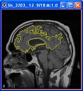
The pointer changes to the cross-hair shape. As you move the pointer, MIPAV determines the level of intensity of the pixel under the cross-hair pointer and uses the results from the Levelset algorithm to determine the probable boundary of the structure. Having determined the probable boundary, MIPAV generates a contour ([MIPAV_Segmentation.html#1010095 Figure 170]). Continue to move the pointer until the structure you wish to outline is contoured.
3 Click the contour to apply it to the structure. See [MIPAV_Segmentation.html#1010095 Figure 170].
|
{| align="center"
|
|
|
Figure 170. Automatically generated contour.
You can now do the following:
Draw an additional contour
Modify the contour
Reassign an existing contour to a different group
Order the contours
Delete the contour
|}
Contouring structures manually
You can contour structures in images by selecting one of MIPAV's predefined shapes, such as a point, straight line, 2D or 3D rectangle, 2D ellipse, interslice VOI, etc. Alternatively, you can use the polygon and polyline tools to draw freehand shapes. For more information about VOIs available in MIPAV, refer to [MIPAV_Segmentation.html#1615758 Figure 171].
Figure 171. VOIs available in MIPAVÂ
 - Point VOI Â
{| align="center"
|
|
Â
|

- Interslice Polyline
Â
{| align="center"
|
|}
|-
|
{| align="center"
|

|}

- Line VOI
|
{| align="center"
|

|}

- Protractor tool
|-
|
{| align="center"
|
|}

- Rectangular VOI
|
{| align="center"
|

|}

- Ellipse VOI
|-
|
{| align="center"
|
|}

- Polygon/Polyline VOI
|
{| align="center"
|
|}

- Levelset VOI
|-
|
{| align="center"
|
|}

- Live wire VOI
|
{| align="center"
|
|}

- 3D rectangular VOI
|}
This section explains how to draw the following:
Point VOIs
VOIs with a straight line
2D rectangular VOIs
3D rectangular VOIs
Ellipsoidal VOIs
Polyline (segmented line) and closed polygon VOIs
Tip: Before you begin, decide whether you want to draw more than one of the same contour in succession. If you do, hold down the Shift key as you select the contour button and draw the contours.
To draw point VOIs
- Draw Point VOI
1 Click the Draw Point VOI button, in the MIPAV window.
2 Move the pointer to the image.
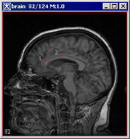
3 Click the area where you want the point to appear. A numbered point appears on the image.
Note: For some algorithms, the sequence in which you draw the points is important (refer to Volume 2 of the User's Guide).
To create VOIs with a straight line
- Draw Line VOI
1 Click the Draw line VOI icon.
2 Click the area on the image where you want the line to begin.
3 Drag the pointer to the place where you want the line to end. As you drag the pointer, the line lengthens.
4 Release the mouse button. The line VOI appears on the image in red.
To create 2D rectangular VOIs
- Draw Rectangular VOI
1 Click the Draw Rectangle VOI icon.
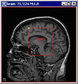
2 Click the area on the image where you want a corner of the rectangle to appear.
3 Drag the pointer. As you drag the pointer, the rectangle changes in size.
4 Release the mouse button when the rectangle is the desired size.
Note: When you create a 2D rectangular VOI, the rectangles appear on only one slice in the dataset.
To create 3D rectangular VOIs
- Draw 3D Rectangular VOI
1 Click the 3D rectangular VOI icon.
2 Click the area on the image where you want a corner of the rectangle to appear.
3 Drag the pointer. As you drag the pointer, the rectangle changes in size.
4 Release the mouse button when the rectangle is the desired size.
Note: Unlike 2D rectangular VOIs, 3D rectangular VOIs appear on all slices in the dataset.
To create ellipsoidal VOIs
- Draw Ellipsoid VOI
1 Click the Draw Ellipse VOI icon.
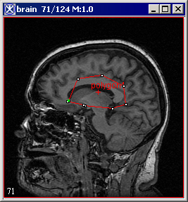
2 Click the area of the image where you want an edge of the ellipse to appear.
3 Drag the pointer. As you drag the pointer, the ellipse changes in size.
4 Release the mouse button when the ellipse is the desired size ([MIPAV_Segmentation.html#1615758 Figure 171]).
To create polyline (segmented line) VOIs or closed polygon VOIs
- Draw Polygon/Polyline VOI
1 Click the Draw Polygon/Polyline VOI icon.
2 Click the area of the image where the polyline VOI should begin.
3 Decide whether to draw either a straight or freehand line segment. Do one of the following:
To draw a straight line segment
Make sure that you have released the mouse button. Move the pointer to the place where you want the segment to end. A straight line, which extends from the starting place to your pointer tip, appears. Click the mouse button to anchor the line segment.
To draw a freehand line segment
Drag the mouse button and move the pointer to the place on the image where you want the segment to end. A line, which matches your mouse movements, extends from the starting place to your pointer tip. Click the mouse button to anchor the line segment.
4 Repeat drawing straight line segments or freehand lines until you finish drawing all of the segments needed to contour the structure.
5 Decide whether to create a polyline VOI or a closed polygon VOI:
Polyline VOI: Go to the next step.
Closed polygon VOI: Click the first anchor point to connect the last line segment to the first, thus forming a closed polygon. Then go to the next step.
6 Click the Default icon, to return the pointer to the default mode.
7 Double-click the mouse button to complete the polyline VOI.
Tip: Depending on which is more comfortable, you can switch between drawing straight line segments or drawing freehand lines at any time.
Tip: To draw multiple VOI, hold Shift while pressing the corresponding VOI icon.
Contouring structures interactively
In the interactive method, you first manually draw a contour that provides a general indication of the location and shape of the structure. You then select an algorithm that analyzes the manually drawn contour and generates a new one that more closely outlines the structure.
To use the interactive method to contour structures, complete the following steps:
1 Draw a contour using one of the manual methods detailed in [MIPAV_Segmentation.html#998415 "Contouring structures manually" on page 260]. The contour need not be precise, but it should indicate the general location and shape of the structure you want to delineate.
2 Select the contour. White anchor points appear on the contour outline.
3 Select one of the following in the MIPAV window:
VOI > Evolve Boundary 2D > Active Contour. This algorithm determines the structure's boundary more quickly than the 2D Spline Active Contour algorithm. It is also more sensitive to noise present in the image. MIPAV applies a gradient magnitude filter to determine the structure's boundary. When complete, the MIPAV-generated contour appears around the structure.
VOI > Evolve Boundary 2D > Active GVF. The Evolve Boundary dialog box uses a special type of active contours, or snakes to find the object boundaries. GVF or the gradient vector flow snake, which is used to calculate VOI boundaries, begins with the calculation of a GVF field of forces by applying generalized diffusion equations to both components of the gradient of an image edge map. Here, GVF fields, are dense vector fields derived from images by minimizing a certain energy functional in a variational framework. The minimization is achieved by solving a pair of decoupled linear partial differential equations that diffuses the gradient vectors of a gray-level or binary edge map computed from the image. See also [MIPAV_Segmentation.html#1617792 Figure 172].
VOI > Evolve Boundary 2D > Spline active contour. This algorithm determines the structure's boundary less quickly than the Active Contour algorithm, however it is less sensitive to noise. This algorithm fits a spline to the data. When complete, the MIPAV-generated contour appears around the structure.
VOI > Evolve Boundary 2D > Spline GVF. This is the combination of the GVF force with the B-spline snake. B-spline snakes have several characteristics which make them well suitable for describing VOI boundary as well as snake evolution: the B-spline implicitly incorporates contour smoothness and avoids the ad hoc tension and rigidity parameters of the traditional GVF snake and also fewer sample points are required to implement contour evolution for the B-spline.
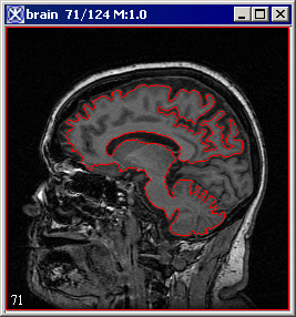
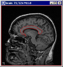
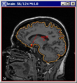
Figure 172. An initial VOI (A) and VOI after applying the Evolve Boundary > Active Contour algorithm with the default parameters (B)
|
{| align="center"
|
|
A
|
{| align="center"
|
|}
B
|}
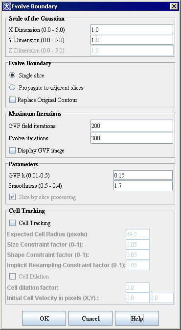
Evolve Boundary dialog box options
|
Scale of the Gaussian
|
A large Gaussian scale slows the snake and causes it to conform to large scale structure. A small Gaussian scale causes the snake to conform to the small scale structure, which is therefore more sensitive to noise.
|
{| align="center"
|
|
|-
|
Evolve Boundary
|
Single Slice - applies the algorithm only on a current image slice.
Propagate to adjacent slices - propagates boundaries to adjacent slices.
Note that the algorithm used for 3D images version is a 2.5D dimensional algorithm where the resultant contour in a slice is projected into the adjacent slice and is used as an initialization to the evolution in the new slice.
Replace original contour - if checked, replaces the original VOI.
|-
|
Maximum Iterations
| rowspan="1" colspan="2" |
GVF field iterations - enter a desired number of GVF iterations here.
Evolve iterations - enter a max number of iterations needed to generate a new VOI boundary.
Display GVF image; if this box is checked, the GVF image appears in a new image frame.
|-
|
Parameters
| rowspan="1" colspan="2" |
GVFk is a positive constant controlling the smoothness of the resulting VOI.
Smoothness corresponds to the balance between internal and external forces. The internal force constrains the snake to be smooth while the external guides the snake to seek desirable image properties, such as edges.
Slice by slice processing - if checked, this activates evolving boundary slice by slice.
|-
|
Cell Tracking
| rowspan="1" colspan="2" |
Cell Tracking - if checked, this box activates the cell tracking algorithm;
Expected Cell Radius (in pixels) - a user-defined cell radius
Size Constraint and Shape Constraint factors are contributed towards the shape and size of the snake in order to make it circular with a user-defined cell radius.
Implicit Resampling Constraint factor minimizes the number of points along the snake curve, thus they maintain an equal distance.
Cell Dilation - if checked, allows dilation
Cell dilation factor is multiple of the cell radius
Initial Cell Velocity in pixels (X,Y)
|-
|
OK
| rowspan="1" colspan="2" |
Applies the parameters that you specified.
|-
|
Close
| rowspan="1" colspan="2" |
Disregards any changes that you made in this dialog box and closes the dialog box.
|-
|
Help
| rowspan="1" colspan="2" |
Displays online help for this dialog box.
|-
| rowspan="1" colspan="3" |
Figure 173. The Evolve Boundary dialog boxÂ
|}
Modifying contours
Once contours are drawn, you can reposition, resize, or reshape them. You can also trim anchor points.
Repositioning contours
You can reposition a single contour or a group of contours. Follow the instructions below.
To reposition a single contour
Select the contour and drag it to the new location.
To reposition a group of contours
1 Hold down the Shift key as you click one of the contours in the group. All of the other contours in the group are also selected.
2 Continue to hold down the Shift key as you drag the contour group to the new location.
Resizing contours
You cannot collectively resize a group that consists of multiple contours; each contour must be resized individually. Except for point VOIs, you can resize any contour shape. For lines, only the length can be changed; the width cannot. To resize lines, go to [MIPAV_Segmentation.html#1392637 ``To resize contours''].
Before you can resize them, all contour shapes except lines must be surrounded by a bounding box. See also the following section [MIPAV_Segmentation.html#1347914 ``To turn the bounding box on''].
To turn the bounding box on
1 Do either of the following:
Select the contour and then select VOI > Properties in the MIPAV window.
Right-click the contour. A menu appears. Select Properties.
The VOI Statistics dialog box opens. See also [MIPAV_Analysis.html#1362684 Figure 196 on page 311].
2 Select Show contour bounding box.
3 Change, if you want, any of the other information in the dialog box.
4 Click Apply.
5 Click Cancel to close the dialog box.
To turn the bounding box off
1 Do one of the following:
Right-click the contour. Select Properties from the pop-up menu.
Left-click the contour. Select Properties from the VOI menu in the MIPAV window.
The VOI Statistics dialog box appears. See also [MIPAV_Segmentation.html#1344987 Figure 174].
2 Clear Show Contour Bounding Box.
3 Click Apply.
4 Click Cancel to close the window.
To resize contours
1 Select the contour. The bounding box appears ([MIPAV_Segmentation.html#1344987 Figure 174]) around the shape. (For rectangle contours, the bounding box and rectangle legs may overlap.)
2 Click Cancel to close the window.
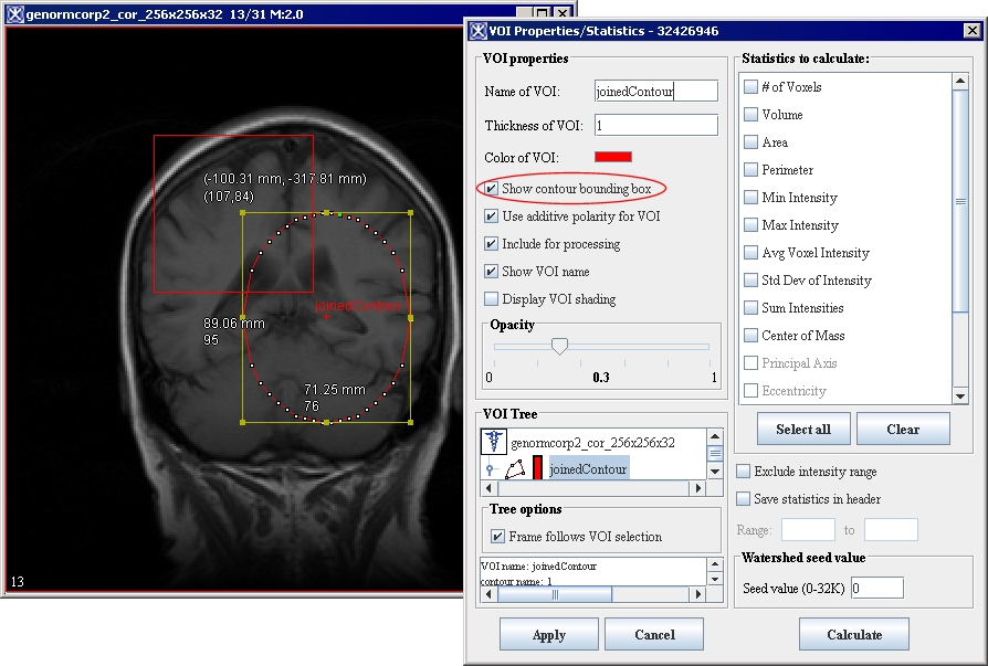
Figure 174. A VOI bounding box and the VOI Properties dialog box
|
{| align="center"
|
|
Â
Â
|}
3 Do one of the following:
To resize lines: Click an edge or corner of the shape. Drag until the shape is the desired size.
To size other shapes: Click one of the bounding box handles. Drag the handle until the shape is the desired size.
4 Choose whether to continue showing the bounding box.
Note: If you want to reposition or add an anchor point, turn the bounding box option off.
Reshaping a contour
You reshape the contour by adding or repositioning anchor points. Instructions for adding and repositioning anchor points follow.
To add anchor points
1 Click the contour to select it. The anchor points become visible.
2 Click the place where you want to add the new anchor point. The new anchor point appears.
To reposition anchor points
You can reposition a single anchor point at a time. If you need to redraw a portion of the contour, MIPAV allows you to reposition several contiguous anchor points with one motion of the mouse.
1 Select the contour. The anchor points become visible.
2 Position the pointer over the anchor point or points that you want to reposition. The pointer changes to the shape of a hand with the index finger extended.
3 Do either of the following:
To reposition a single anchor point: Drag the anchor point to the new location.
To reposition several anchor points: Hold down the Alt key as you drag the anchor points in the counterclockwise direction to their new locations.
Retracing a VOI contour
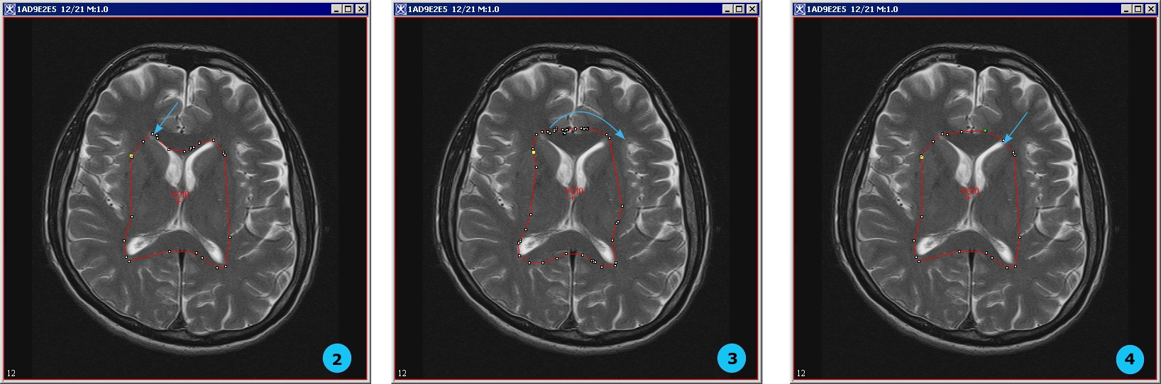
To retrace a VOI contour do the following (see [MIPAV_Segmentation.html#1657248 Figure 175]):
1 Select an existing VOI;
2 Hold the ALT key and use the mouse to pick up a point on the VOI;
3 While holding both the ALT key and left mouse button, move the mouse clockwise to redraw the VOI;
4 Stop moving when you reach the last point which you would like to redraw.
Figure 175. Retracing a VOI contour
|
{| align="center"
|
|
|}
Trimming VOI anchor points
MIPAV can automatically trim anchor points from the contour. In the trimming process, unnecessary anchor points are pruned. For example, if three anchor points are on the same line, the middle anchor point is deleted. Since only two anchor points are needed to indicate a line, the middle anchor point is extraneous. The trim parameter defines what is meant by the same line. Setting this value to zero causes only unnecessary anchor points on a straight 180-degree line to be pruned. Setting a higher value prunes all but the sharpest corners of the contour.
To trim anchor points
1 Select the contour you want to trim.
2 Select VOI > Trim Parameter in the MIPAV window. The VOI Trim Parameter dialog box ([MIPAV_Segmentation.html#1011435 Figure 176]) opens.
3 Move the slider to the desired number.
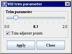
Figure 176. VOI trim parameter dialog box
|
Trim parameter
|
Specifies the number of anchor points you want the software to trim from the contour. Setting this value to zero causes only unnecessary anchor points on a straight 180-degree line to be pruned. Setting a higher value prunes all but the sharpest corners of the contour.
|
{| align="center"
|
|
|-
|
Trim adjacent points
|
Trims points that are adjacent.
|-
|
Apply
| rowspan="1" colspan="2" |
Applies the parameters that you specified.
|-
|
Close
| rowspan="1" colspan="2" |
Disregards any changes that you made in this dialog box and closes the dialog box.
|-
|
Help
| rowspan="1" colspan="2" |
Displays online help for this dialog box.
|}
4 Click Apply. The software removes all unnecessary anchor points.
5 Click Close to close the dialog box.
Grouping and ordering contours
By default, when you draw multiple VOIs they appear grouped in a single group, and therefore all colored in the same color. To ungroup VOIs, select one VOI from the group, and then call VOI>VOI Grouping>Group VOIs. This will ungroup VOIs and they appear in the image in different colors. To group VOIs, select the VOIs which you would like to group (use Ctrl Shift right mouse combination of keys for multiple selection), and then call VOI>VOI Grouping>Group VOIs. This will group selected VOIs and they all appear in the image colored in the same color.
Grouping contours
A group may consist of one or more contours. A contour is assigned to only one group. When a contour is initially drawn or generated, MIPAV assigns it to a default group. MIPAV also assigns default group properties, such as color and name. Each contour inherits the properties of its assigned group. At any time, you can change the properties of a group or its members (contours).
To change the group with which a contour is affiliated
1 Right-click the contour you wish to modify.
2 Select Properties. The VOI Statistics dialog box opens. See [MIPAV_QuickStart.html#2759314 Figure 33].
The name of the VOI appears in the Name of VOI text box. A colored box appears beside the text box.
To change group properties
1 Select the colored box on the VOI Statistics dialog box. The Pick VOI Color dialog box opens.
2 Click OK to apply the color to the grid/border. The Pick VOI color dialog box closes.
3 Click OK.
To change the name of the VOI, modify the name in the text box next to the Name of VOI colored box.
To adjust the opacity, move the slider in the Opacity panel. The number in the center indicates the current value; 0 is transparent and 1 is opaque.
Splitting VOI contours
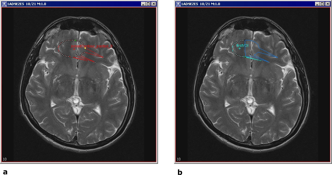
A VOI can be divided into two or more contours using the Split VOI Contour icon. Any contour that is initially drawn or generated can be spitted into two contours using that tool. For result VOIs, MIPAV assigns default VOI properties, such as color and name. By default, the result VOIs have the following names: firstVOI and secondVOI.
Each result contour inherits the properties of its parent VOI. However, at any time, you can change the properties of result contours using the standard MIPAV tools (see [MIPAV_Segmentation.html#998415 "Contouring structures manually" ]).
To split a VOI
1 Select the VOI.
2 Click the Split VOI Contour icon on the VOI toolbar, the mouse cursor changes to " ".
3 In the image, use the mouse to draw the line splitting the VOI into two.
4 In the Split VOI dialog box that appears, specify if you want to split the VOI in all slices or only in the active slice. Press Split.
The result VOIs appears in the image, see [MIPAV_Segmentation.html#1656774 Figure 177].
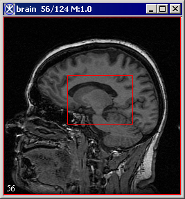
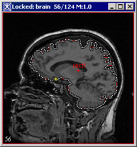
Figure 177. Splitting a VOI: (a) the initial VOI and (b) the two result contours
|
{| align="center"
|
|
|}
Ordering contours
If two or more contours overlap, MIPAV organizes them so that they appear one on top of the other, much like a stack of papers on a desk. This is often not readily apparent because, by default, when contours are drawn, they are transparent and only the outlines are visible. Thus, if two contours overlap, all parts of each contour, except the areas where the outlines overlap, can be seen.
To fill contours
1 Right-click the contour.
2 Select Properties. The VOI Statistics dialog box opens. See also [MIPAV_Analysis.html#1362684 Figure 196 on page 311].
3 Clear the Boundary or Blended check box to remove the check mark, then click Apply.
4 Close the VOI Statistics dialog box. The contour is filled with the default paint color. To change the paint color, refer to [MIPAV_Segmentation.html#1348003 "Manually creating a mask using paint" on page 282].
To arrange contours
1 Click the contour to be reordered. See [MIPAV_Segmentation.html#1631684 Figure 178].
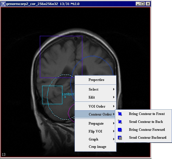
2 Select the Contour Order context menu. Then select one of the following commands:
Bring to Front: Moves the contour in front of all of the other contours.
Send to Back: Moves the contour behind all other contours.
Bring Forward: Moves the contour forward one position. For example, if you select this command and the contour is the third contour in a stack of five contours, the contour is moved to the second position in the stack.
Send Backward: Moves the contour backward one position. For example, if the contour is the third contour in a stack of five contours, the contour is moved to the fourth position in the stack.
The software reorders the contours according to the command.
Figure 178. Arranging the VOIs
|
{| align="center"
|
|
|}
Smooth VOI
To smooth a VOI, select it first, and then call VOI > Smooth VOI. The Smooth VOI dialog box opens. This dialog sets the parameters and then calls the algorithm for smoothing the VOI. In the dialog box, you can specify the following:
Whether or not to remove the original selected VOI;
Whether or not to apply trimming to remove nearly collinear points;
A number of interpolation points.
In 2D images all selected curves of a selected VOI are smoothed. In 3D images all selected curves in all slices of a selected VOI are smoothed. The original Z-slice information is only used so that the default number of interpolated points comes from a contour in a Z-slice.
If the original VOI was not removed, the new VOI has a new color. If the original VOI was removed, the new VOI has the same color as the original VOI had.
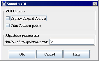
Figure 179. Smooth VOI dialog box
|
Replace Original Contour
|
If selected, this option allows a new smoothed VOI to replace the original VOI.
|
{| align="center"
|
|
|-
|
Trim Collinear Points
|
If selected, it allows to trim points that are adjacent.
|-
|
Number of Interpolation Points
|
Enter the number of interpolation points that will used to calculate a new smoothed VOI.
|-
|
OK
| rowspan="1" colspan="2" |
Applies the parameters that you specified.
|-
|
Close
| rowspan="1" colspan="2" |
Disregards any changes that you made in this dialog box and closes the dialog box.
|-
|
Help
| rowspan="1" colspan="2" |
Displays online help for this dialog box.
|}
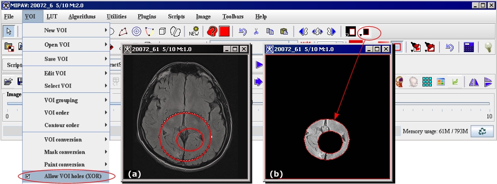
Allow VOI holes (XOR)
This option (if turned on) allows to preserve holes in VOIs when converting them to masks (see [MIPAV_Segmentation.html#1611149 ``Converting VOI contours to masks'']), see [MIPAV_Segmentation.html#1652333 Figure 180].
Figure 180. The Allow VOI holes (XOR) option is turned on
|
{| align="center"
|
|
|}
The algorithm uses the XOR operation, for more information, refer to ``Morphology''.
Copying, cutting, and pasting VOIs
You can undo, cut, copy, and paste a VOI within the image, to another slice in the image dataset, or to another image dataset.
To undo a VOI
1 Select the VOI.
2 Select Edit > Undo VOI in the MIPAV window. The software removes the VOI from the image.
To cut a VOI
1 Select the VOI.
2 Select Edit > Cut VOI in the MIPAV window. The software copies the VOI to the clipboard and deletes it from the window.
Tip: You can also remove a VOI by pressing the Del key after selecting the VOI.
To copy and paste a VOI
1 Select the VOI.
2 Select VOI> Edit VOI> Copy VOI. It is copied to the clipboard.
3 NOw, do one of the following:
Navigate to another slice using the Image Slice Slider.
Or open another image dataset.
4 Select VOI > Edit VOI > Paste VOI. The program copies the VOI from the clipboard and pastes it into the image.
You can only copy and paste a single, not multiple, VOIs into another slice using the Paste command. Also, note that the software pastes a copied VOI into the image at exactly the place from which it was copied.
To propagate multiple VOIs to the next or previous slice in the dataset
 - Propagate Both Sides;
  - Propagate Left;
  - Propagate Right;
1 Select all of the VOIs that you want to copy.
2 Do one of the following:
Click the Propagate VOI up icon, to copy the VOI to the next slice.
Click the Propagate VOI down icon, to copy the VOI to the previous slice.
Click the Propagate VOI to all slices icon, to copy it to every image in the dataset.
Deleting VOIs
You can easily delete a VOI or one of its contours.
To delete a VOI
1 Select the VOI or one of its contours.
To delete a VOI that consists of many contours, hold down the Shift key and then click one of the contours in the VOI group.
2 Do one of the following:
Right-click on the VOI, and then select Edit > Delete.
Select Edit > Delete VOI in the MIPAV window.
The software removes the VOI or contour.
Saving and opening VOI files
You can save a VOI to a text file. This file can then be opened and applied to the same dataset or a different one, or it can be manipulated using a word processor.
To save a single VOI as a text file
1 Select a contour or a VOI.
To select a contour, click on it.
To select a VOI, hold down the Shift key and select a contour. All contours that are part of the VOI are selected.
2 Do either of the following:
If you want the software to automatically name the file, select VOI > Save VOI in the MIPAV window. The software saves the file with an.XML extension.
If you want to assign the file name, select VOI > Save VOI as. The Save as dialog box appears.
a Type the name of the VOI file in the File Name box. Be sure to use either the VOI extension or the XML extension.
b Click Save. The software saves the file under the specified name.
To save multiple VOIs
Do either of the following:
To allow the software to automatically name the file, select VOI > Save All VOIs.
To assign a file name to the file, select VOI > Save All VOIs as.
a Type the name of the VOI file in the File Name box. Be sure to use either the VOI extension or the XML extension.
b Click Save. The software saves the file under the specified name.
To open saved VOI files
1 Select the image window of the dataset to which you want to apply the VOI.
2 Select VOI > Open VOI in the MIPAV window. The Open dialog box appears.
3 Select the file or files and then click Open. The VOI or VOIs appear in the image window.
Note: If you make a change to the VOI and want to make a change to the file, select VOI > Save VOI in the MIPAV window. The changes are saved to the VOI file.
Segmenting Images Using Contours and Masks: Generating Masks


