Displaying images using the triplanar-dual view
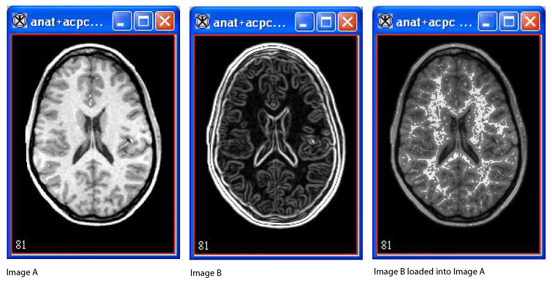
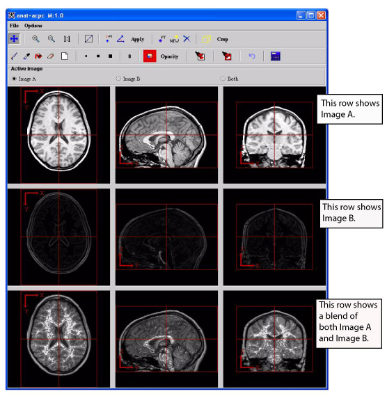
The triplanar-dual view displays two image datasets (referred to as Image A and Image B) and a blended version of both Image A and Image B from three orthogonal planes.
To view image datasets using this view
1 Open two 3D or 4D images, which become known as Image A and Image B.
2 Load Image B into Image A.
3 Select Image > Views > Triplanar-Dual. The triplanar-dual view appears in an image window.
Figure 1. Image A, Image B, and Image B loaded into Image A
|
|
The image window for the triplanar-dual view is quite similar to the image window for the triplanar view. The File and Options menus contain the same commands except for one command-the Options menu for the triplanar view contains the command Link to Another TriImage. Since the triplanar-dual view shows two datasets in the image window and allows you to manipulate them together, linking to another image is not necessary. Most of the icons and buttons on the toolbars for both views are the same with one primary difference: The triplanar-dual view allows you to create VOIs on the images; the triplanar view does not.
Like the triplanar view, you can use the icons and buttons on the toolbar to change magnification, draw, change colors, change opacity, and apply a new intensity to selected voxels in the images.
Showing and hiding axes, cross hairs, and Talairach grid
By default, the triplanar-dual view automatically shows the axes and cross hairs on Image A, Image B, and the blended dataset.
To show or hide axes on images
To hide the axes, select Options > Show Axes (Figure 2). The check mark disappears from the check box in front of the command on the menu, and the axes disappear from all of the images.
Figure 2. Show Axes command on the Options menu in the Triplanar-Dual window
|

|
To display the axes on the images again, simply select Options > Show Axes. The check mark reappears in the check box in front of the command.
To show or hide cross hairs
Showing or hiding cross hairs works just as showing or hiding axes. To hide the cross hairs, select Options > Show Cross Hairs. To show them, select Options > Show Cross Hairs again.
To show or hide the Talairach grid
By default, the Talairach grid does not automatically display on the images unless you specifically select it to do so. To show the grid, select Options > Show Talairach Grid. The grid appears on all of the images shown in the triplanar-dual view. When you want to hide the grid, select Options > Show Talairach Grid again.
Creating VOIs on images
You can create point or line VOIs on the images.
To create point VOIs
1 Click  .
.
2 Click in the image where you want to create a point.
3 Repeat steps 1 and 2 for all other desired points.
To draw line VOIs
1 Click  .
.
2 Click in the image where the line should begin and drag the line to where it should end.
The numbers beneath the line indicate the length of the line in millimeters.
To change the line VOI, simply click on the VOI and then drag it to another position in the image.
Note: You can only create one line VOI per orthogonal plane, although you can create a line VOI in each one of the three orthogonal planes.
To delete line VOIs
You cannot delete a line VOI. However, you can remove the display of the line VOI on the image. To do so, click  . The line VOI disappears.
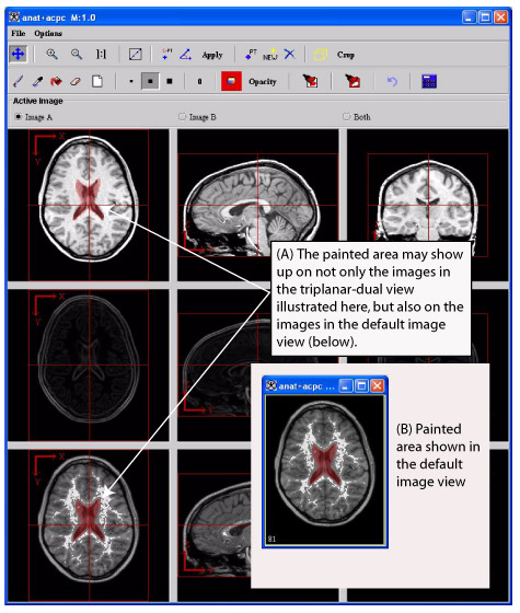
Figure 3. Triplanar-Dual window
|
|
|
File
|
Close Frame-Closes this window.
|
|
Options
|
Show Axes-Displays the XY (top left), ZY (top right), and ZX (bottom left) axes on the images.
|
|
Show Cross Hairs-Displays the cross-hair lines on the images. When you move these lines on one image, it also moves to the corresponding points all of the other images.
|
|
Show Talairach Grid-Displays a Talairach (stereo tactic) grid on the images.
|
 Traverse image Traverse image |
Aligns two images.
|
 Magnify image 2.0x Magnify image 2.0x |
Enlarges the images to twice their current size. It might be necessary to manually resize the window and use scroll bars to view all of the images.
|
 Magnify image 0.5x Magnify image 0.5x |
Reduces the images to half of their current size.
|
 Magnify image 1.0x Magnify image 1.0x |
Restores the images to their original size.
|
 Draw line VOI Draw line VOI |
Draw a line VOI.
|
 Identify center of volume Identify center of volume |
Reassigns a new center to each dataset. The location that you select appears in the center of each image.
|
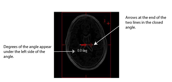
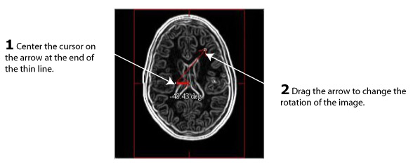
 Alignment tool Alignment tool |
Allows you to apply a transformation matrix to an image dataset.
|
 Applies rotations and translations Applies rotations and translations |
Applies the rotations and translations made to the images.
|
 Add point Add point |
Draws a point on an image. This point is only on the image you select.
|
 Initiate new VOI Initiate new VOI |
Indicates that the next VOI is a new VOI rather than a change to the currently existing VOI.
|
 Delete point VOI Delete point VOI |
Removes the point VOI from the image.
|
 Identify crop volume Identify crop volume |
Displays the bounding box, which is outlined in red, on each image.
|
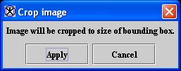
 Crops image delineated by the bounding cube Crops image delineated by the bounding cube |
Displays in a separate image window only the area enclosed by the bounding box. When you click this icon, the Crop Image dialog box opens.
|
|
 Draw using a brush Draw using a brush |
Allows you to draw with a brush on the image.
|
 Picks up a color from the image Picks up a color from the image |
Changes the color of the paint used to the color selected on the image.
|
 Fills an area with desired color Fills an area with desired color |
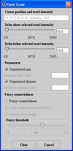
Allows you to fill an area with color. When you select this icon, the Paint Grow dialog box opens.
|
 Erases a portion of the image Erases a portion of the image |
Removes the paint from the specific spot that you select.
|
 Erase all paint Erase all paint |
Removes all paint from all of the images.
|
 Draw using small size Draw using small size |
Indicates the size of the paint brush tip. Click this icon to paint one voxel each time the mouse button is clicked.
|
 Draw using medium size Draw using medium size |
Indicates the size of the paint brush tip. Click this icon to paint 16 voxels (4 x 4 square) each time the mouse button is clicked.
|
 Draw using large size Draw using large size |
Indicates the size of the paint brush tip. Click this icon to pain 100 voxels (10 x 10 square) each time the mouse button is clicked.
|
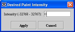
 Change intensity level of paint Change intensity level of paint |
Allows you to change the intensity value of the paint. When you click this icon, the Desired Paint Intensity dialog box opens.
{| align="center"
|
|
You can specify an intensity between -32,768 and 32,767. After you type an intensity level, the icon displays the level you entered.
|-
|
 Change paint color
| rowspan="1" colspan="2" |
Changes the color of the paint used. This icon is often used in conjunction with the Draw icons. When you click this icon, the Pick Paint Color dialog box opens. After you change the color, this icon displays the color.
|-
|
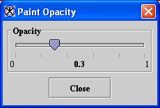
 Opacity
| rowspan="1" colspan="2" |
Allows you to change the opacity of the paint. When you click this icon, the Paint Opacity dialog box opens.
{| align="center"
|
|}
|-
|
 Changes image where painted
| rowspan="1" colspan="2" |
Permanently applies the intensity level to the images.
|-
|
 Undo last region paint
| rowspan="1" colspan="2" |
Removes paint from the last area to which it was applied.
|-
|
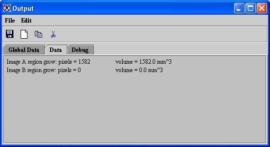
 Calculate volume of paint
| rowspan="1" colspan="2" |
Determines the volume, or number of pixels, in the painted area of the image.
|-
|
 Image A
| rowspan="1" colspan="2" |
Performs the action only on Image A.
|-
|
 Image B
| rowspan="1" colspan="2" |
Performs the action only on Image B.
|-
|
 Both
Both| rowspan="1" colspan="2" |
Performs the action on both Image A and Image B.
|}


