MIPAV configuration files
Contents
Preference file
What is its purpose?
You can customize the settings in the file by selecting Help > Program Options in the MIPAV window. For example, you can change whether the splash screen appears when you start the program, whether the scripting toolbar appears, the color of the crosshair cursor, whether the log mode is turn on, and so on.
When and how is it created?
MIPAV generates a preference file for all users when the program is run for the first time. Usually, the first settings recorded in the preference file are the memory setting, or maximum heap size, and the default image directory. When you first customize one or more of the settings in the Program Options dialog box, MIPAV adds those settings to the preference file as well as the default settings for those features you did not change. If you later make changes to those same preferences, the program adds those new settings to the preference file. In other words, the initial preference file is very small. It grows in size as you customize the program with the latest changes appearing last in the file.
Where is it stored?
By default, MIPAV stores the preference file in your home directory.
|
For . . .
|
The home directory is . . .
|
|
Window users
|
C:\Documents and Settings\userID
|
|
Unix users
|
Â
|
|
MacIntosh users
|
Â
|
However, if MIPAV is installed on a network and several users access it remotely, preference files are stored in the network home directory.
|
1 2 3 4 5 6 7 8 9 10 11 12 13 14 15 16 17 18 19 20 21 22 23 24
|
# MIPAV preference file #Mon Mar 19 15:12:48 EST 2001 LightBoxGridRow=2 LightBoxBorderSize=3 EnableDICOMReceiver=true TRIM=0.4 DEBUG=true PlugInFile3=SpreadSheet PlugInFile2=GraphPanel PlugInFile1=Chart Swing=true LightBoxRowDependant=true PlugInView1=DrawTest PlugInAlgorithm1=GraphApplet Server1=MRIPS;MARS;137.187.26.152;104; Storage1=MIPAV;MIPAV;C\:\\images;3100 SplashGraphics=no LightBoxGridColor=000000 LightBoxBorderColor=960000 LightBoxGridSize=5 LightBoxMagnification=45.0 LightBoxGridCol=2 ImageDirectory=D\:\\Java\\jdk1.3\\demo\\applets\\SpreadSheet LightBoxLocation=813,23
|
|
1-2
|
Indicate the type of file and the date and time of the last update (comment lines).
|
|
3-4
|
Indicate default settings the light box image window.
|
|
5
|
Shows DICOM information and indicates whether the DICOM Receiver is on by default. If the DICOM Receiver is on, you can receive or retrieve DICOM image files.
|
|
6
|
Indicates the default trim parameter. The trim parameter is discussed in detail in Chapter 7.
|
|
7
|
Indicates whether MIPAV is placed in debug mode. If MIPAV is placed in debug mode and technical problems occur while you use the software, error messages are logged in the Output window.
|
|
11
|
Indicates whether the Swing-generated graphical user interface (GUI) is displayed. If the preference is set to false, the Advanced Windows Toolkit (AWT)-generated GUI appears instead.
|
|
12
|
Indicates default settings the light box image window.
|
|
13-14
|
Shows plug-in file information.
|
|
15-16
|
Shows DICOM information and shows hosts table entries. (The hosts table is located in the DICOM Communication Panel window.) Line 15 shows the server (device) entry. Line 16 shows a storage destination entry, which indicates where image files are stored when they are received or retrieved. If you indicate more than one storage destination entry, more lines appear in the preference file. For more information on MIPAV`s DICOM capabilities, refer to [MIPAV_DicomImages.html#1259465 "Working with DICOM Images" on page 85].
|
|
16
|
Shows DICOM information.
|
|
17
|
Indicates whether an introductory splash screen appears when you start MIPAV.
|
|
18-22
|
Indicates default settings the lightbox image window.
|
|
23
|
Shows the image directory.
|
LUT file
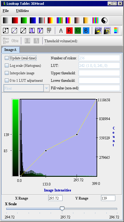
What is its purpose? The lookup table (LUT) file holds lookup table values, which you can modify, for the active image currently being displayed. When and how is it created? MIPAV generates the file when, after opening an image, you do the following:
|}
By default, the LUT file is stored in the same directory that holds the image.
[MIPAV_AppCSupportedFormats.html#1248570 Figure 6] is an example of a LUT file. The middle section of the file was removed in this example because of space limitations, and the column headings-alpha, red, green, and blue-were added to make it is easier to interpret the values. The column headings do not appear in the actual LUT file.
|
Alpha Red Green Blue <LUT> 256 # Size of LUT Arrays 0 1.0 0.0 0.0 0.0 1 1.0 0.99609375 0.99609375 0.99609375 2 1.0 1.9921875 1.9921875 1.9921875 3 1.0 2.9882812 2.9882812 2.9882812 4 1.0 3.984375 3.984375 3.984375 5 1.0 4.9804688 4.9804688 4.9804688 6 1.0 5.9765625 5.9765625 5.9765625 7 1.0 6.9726562 6.9726562 6.9726562 8 1.0 7.96875 7.96875 7.96875 9 1.0 8.964844 8.964844 8.964844 10 1.0 9.9609375 9.9609375 9.9609375 11 1.0 10.957031 10.957031 10.957031 12 1.0 11.953125 11.953125 11.953125 13 1.0 12.949219 12.949219 12.949219 14 1.0 13.9453125 13.9453125 13.9453125 [This part of the LUT file was removed to save space.] 251 1.0 250.01953 250.01953 250.01953 252 1.0 251.01562 251.01562 251.01562 253 1.0 252.01172 252.01172 252.01172 254 1.0 253.00781 253.00781 253.00781 255 1.0 254.0039 254.0039 254.0039 Â
|
