Filters (Spatial): Mean
This algorithm provides a simple way of reducing noise either in an entire image or in a delineated VOI in the image where
- Mean = sum of all pixels in the kernel / total number of pixels in the kernel
This is one method of low-pass filtering, which is sometimes referred to as neighborhood averaging.
Contents
Background
In applying this algorithm, MIPAV first defines a region, either in the whole image or in the delineated VOI, over which it replaces a target pixel value with the average value over the kernel of pixels in which the target pixel is at the center. That is, for the target pixel:
<math> mean = \frac {1} {s} \sum_{i=1}^{i=s} I_i k_i </math>
where k '= kernel,' s = kernel size, and I = image.
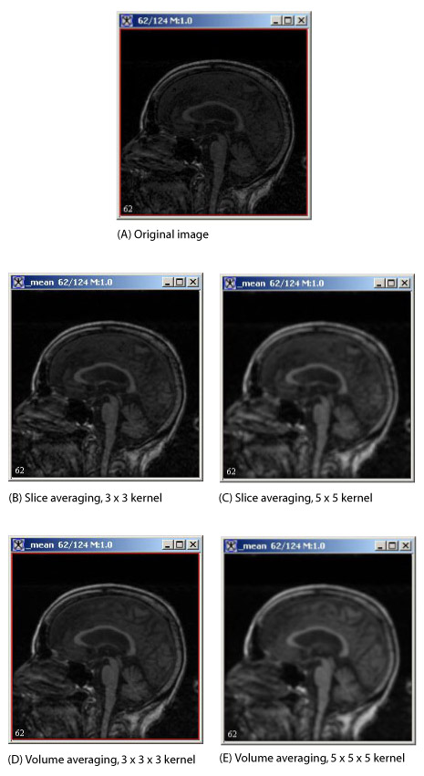
For slice averaging (Figure 1] and (Figure2), the kernels are odd-length squares (for example, 3 x 3). The processing time increases with the square of the kernel length. For volume averaging ( Figure 2), the kernels are odd-length cubes (such as 5 x 5 x 5), and the processing time increases with the cube of the kernel length. Refer to Figure 2 for examples of slice and volume averaging.
Note that the term average does not always represent the mean. If fact, there are three types of average: the commonly used mean, the median, and the infrequently used mode. The mean is defined as the sum of the values in a group divided by the number of values in the group. The median value is the value that has the same number of values greater and less than it. The mode is the value with the greatest number of occurrences.
If part of the neighborhood kernel falls outside the image when the pixel is on or near the boundary, MIPAV only uses that portion of the kernel inside the image.
| Example: Consider the upper right corner pixel in a 2D image if a 3 x 3 kernel is used. In this case, when the algorithm is applied, MIPAV uses only the target pixel and its lower, left, and diagonal left lower neighbors. It then divides the sum of these four pixels by 4. |
If you select the New image option, MIPAV places the resulting image in a new image window. If you select the Replace image option, MIPAV returns the changed picture to the same image window. If you delineate a VOI on the image and select VOI regions, then MIPAV replaces the original value of a pixel inside the VOI with the mean value of the kernel that contains the pixel at its center. The pixel values outside the VOI remain unchanged.
Because 2D images contain only one slice, the only option possible under Kernel Thickness in the Mean Filter dialog box is slice averaging-the Apply slice kernel option. The Apply volume kernel option, which performs volume averaging, is dimmed. However, both slice averaging and volume averaging are available for 3D images. Although slice averaging is the default value, users can choose volume averaging instead by selecting the Apply volume kernel option.
For slice averaging, the default kernel size is 3 x 3, but the following kernel sizes are available: 5 x 5, 7 x 7, 9 x 9, or 11 x 11. For volume averaging, the default kernel size is 3 x 3 x 3. However, you can select one of the following sizes instead: 5 x 5 x 5, 7 x 7 x7, 9 x 9 x 9, or 11 x 11 x 11.
For color images the default is to obtain the means of the red, green, and blue channels. However, if users clear the Red channel, Green channel, or Blue channel check boxes, MIPAV only performs mean averaging on the color channels that are selected.
Image types
You can apply this algorithm to all image data types and to 2D, 2.5D, and 3D images.
Special notes
None.
References
Refer to the following reference for more information about this algorithm:
Raphael C. Gonzalez and Richard E. Woods. Digital Image Processing, Second Edition (Upper Saddle River, New Jersey: Prentice-Hall, Inc., 2002), pp. 116-123.
Applying the Mean algorithm
To run this algorithm, complete the following steps:
- Open an image. As an option, delineate a VOI.
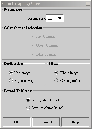
- Select Algorithms > Filter (spatial) > Mean. The Mean Filter dialog box (Figure 3) opens.
- Complete the information in the dialog box.
- Click OK.
- The algorithm begins to run, and a pop-up window appears with the status. The following message appears
- "Filtering image."
- When the algorithm finishes running, the pop-up window closes, and the results either appear in a new window or replace the image to which the algorithm was applied.
|
Kernel size
|
Specifies the size of the k x k neighborhood that extends in all directions by (k - 1)/2 from the center pixel.
|
|
|
Red channel
|
Applies the algorithm to the red channel.
| |
|
Green channel
|
Applies the algorithm to the green channel.
| |
|
Blue channel
|
Applies the algorithm to the blue channel.
| |
|
New image
|
Shows the results of the algorithm in a new image window.
| |
|
Replace image
|
Replaces the current active image with the newly calculated mean image.
| |
|
Whole image
|
Applies the algorithm to the whole image.
| |
|
VOI regions
|
Applies the algorithm to the volumes (regions) delineated by the VOIs.
| |
|
Apply slice kernel
|
Applies the kernel to only the specific slice in the dataset
| |
|
Apply volume kernel
|
Applies the kernel to all of the slices-that is, the entire volume-in the dataset.
| |
|
OK
|
Applies the mean algorithm according to the specifications in this dialog box.
| |
|
Cancel
|
Disregards any changes that you made in this dialog box and closes the dialog box.
| |
|
Help
|
Displays online help for this dialog box.
| |

