Delineating volumes of interest (VOIs)
Contents
Delineating volumes of interest (VOIs)
MIPAV provides tools that allow you to automatically, semiautomatically, and manually identify and modify volumes of interest (VOIs).
volume of interest-the portion of the image in the dataset on which you want to focus. It may be either one slice or multiple slices throughout the dataset.
Each VOI can be formed from multiple contours in a single slice or multiple slices. Once an object is segmented and defined by a VOI, statistics of the volume can be calculated.
MIPAV supports over 32,000 unique VOIs on a single dataset. Additionally, you can move or delete nodes on the VOI and add new points. VOI types include:
- Point, which is created by using
- 2D line
- Rectangular
- 3D rectangular
- 2D elliptical
- Polygonal
- 3D polygonal
- Interactive level-set
Generating contour VOIs using predefined shapes
MIPAV includes icons of predefined shapes, such as points, lines, ellipses, or rectangles, that you can use to create VOIs. These icons are on the VOI toolbar.
To generate contour VOIs using the predefined shapes
1 Select one of the contour icons from the VOI toolbar in the expanded MIPAV window. See also Figure 12.
</font></div>
Adding and moving boundary points on VOIs
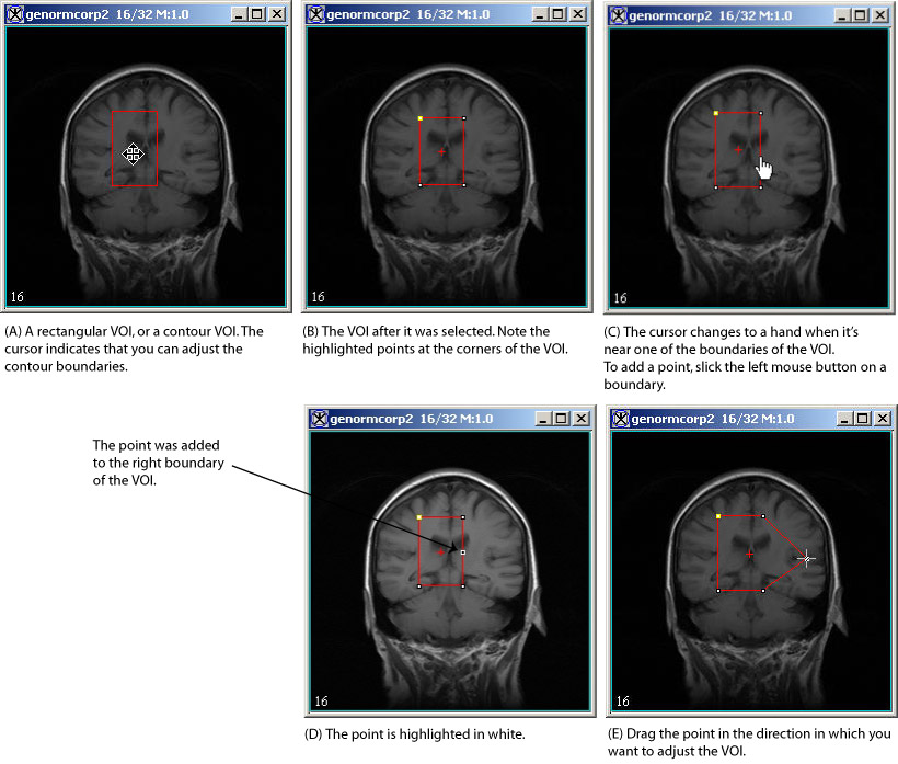
No matter which method chosen to delineate a VOI, you can add points and change the boundaries of the VOI. For example, suppose you created a VOI on an image with the Rectangle VOI icon. If you notice that a part of the image that should be included in the VOI is not included, the boundary of the rectangle needs to be adjusted to include the missing portion of the image.
To add a point and change the boundary of the VOI
1 ![]() Select the VOI. Notice that white points appear at the corners of the VOI and a small cross appears in the middle of the VOI.
Select the VOI. Notice that white points appear at the corners of the VOI and a small cross appears in the middle of the VOI.
2 ![]() Place the cursor on the portion of the VOI you want to adjust. The cursor changes from a cross to.
Place the cursor on the portion of the VOI you want to adjust. The cursor changes from a cross to.
3 Click once. A white point appears on the line.
4 Select the point and drag it to include the missing part of the image.
Tip:Circular VOIs are composed of a continuous series of points around the diameter of the circle. You only need to select one of those points and drag it to enlarge the circle.

|
Automatically adjusting contour boundaries
After a contour is drawn, it might be necessary to adjust the boundaries so it more closely matches the VOI region.
To adjust contours
1 Click a contour. The nodes become visible.
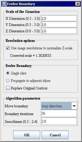
2 Select VOI > Evolve boundary 2D >Active Contour. The Evolve Boundary dialog box opens.
3 Modify the information in the window if necessary.
4 Click OK.
A new contour, that more closely outlines the VOI, appears on the image. The old contour also remains.
![]() To delete an old contour, select the contour, and then select Cut Selected Contour, or press the Del key on the keyboard.
To delete an old contour, select the contour, and then select Cut Selected Contour, or press the Del key on the keyboard.
|
Scale of the Gaussian
|
Enter values for X,Y, and Z directions which will be used to correct blurring. The default value is 2.0
|
|
| Resolution options | If this box is checked, the algorithm uses the image resolution to normalize the Z scale. | |
| Evolve Boundary | Replace Original Contour - the original VOI will be replaced with the new one. | |
| Algorithm parameters | Move Boundary - depending on the selected option, the VOI will be moved in 1) any direction, 2) only inward, 3) only outward. Boundary Iterations- specify the number of iterations needed to calculate the new boundary. Smoothness- enter the number from 0.5 to 2.4 to specify smoothness. | |
| OK | Applies the algorithm according to the specifications in this dialog box. | |
| Cancel | Disregards any changes that you made in this dialog box and closes it. | |
| Help | TBD. |
