Cropping images and Customizing the appearance of graphs - Modify graph dialog box: Difference between pages
m (1 revision imported) |
m (1 revision imported) |
||
| Line 1: | Line 1: | ||
You can adjust the appearance of graphs to interpret the information more clearly or easily. To customize graphs, you use the Modify Graph dialog box , which is accessible through Views > Modify Graph Features in both the Contour VOI window and the Intensity Graph window. The Modify Graph dialog box includes the following four tabbed pages: <br /> | |||
* ''Graph tab'', which allows you to show or hide the gridlines and tick marks, change the number of gridlines and background color of the graph, change the labels on the graph, and change the range values.<br /> | |||
You can use the | * ''Legend tab'', which lets you determine whether a legend should appear on the graph and allows you to assign a specific name to each function.<br /> | ||
* ''Functions tab'' , which allows you to change the appearance of the functions in the graph. <br /> | |||
* ''Fitted Functions tab'', which allows you to modify the functions.<br /> | |||
'' | |||
{| border="1" cellpadding="5" | {| border="1" cellpadding="5" | ||
|+ '''Figure | |+ '''Figure 13. The Graph page of the Modify Graph dialog box ''' | ||
|- | |||
| rowspan="1" colspan="3" | | |||
<div class="CellBody">Graph tab</div> | |||
|- | |- | ||
| | | | ||
<div class="CellBody"><span style="font-style: normal; text-decoration: none; text-transform: none; vertical-align: baseline">'''<font color="#000000">Gridlines visible</font>'''</span></div> | |||
| | |||
<div class="CellBody">Displays, if selected, gridlines on the graph in the Intensity Graph window. </div> | |||
| rowspan="3" colspan="1" | | |||
[[Image:VOIGraphsModifyGraphGraph.jpg]] | |||
|- | |- | ||
| | | | ||
<div class="CellBody"><span style="font-style: normal; text-decoration: none; text-transform: none; vertical-align: baseline">'''<font color="#000000">Minor tick marks visible</font>'''</span></div> | |||
| | |||
<div class="CellBody">Displays, if selected, the tick marks on the <span style="font-weight: normal; text-decoration: none; text-transform: none; vertical-align: baseline">''<font color="#000000">X</font>''</span> and <span style="font-weight: normal; text-decoration: none; text-transform: none; vertical-align: baseline">''<font color="#000000">Y </font>''</span>axes of the graph in the Intensity Graph window.</div> | |||
|- | |- | ||
| | | | ||
<div class="CellBody">Indicates the | <div class="CellBody"><span style="font-style: normal; text-decoration: none; text-transform: none; vertical-align: baseline">'''<font color="#000000">Number of X-axis gridlines</font>'''</span></div> | ||
| | |||
<div class="CellBody">Indicates the number of gridlines that appear on the <span style="font-weight: normal; text-decoration: none; text-transform: none; vertical-align: baseline">''<font color="#000000">X</font>''</span> axis of the graph. The default number of gridlines is 4. You can specify from 1 to 50 gridlines. </div> | |||
|- | |- | ||
| | |||
<div class="CellBody"><span style="font-style: normal; text-decoration: none; text-transform: none; vertical-align: baseline">'''<font color="#000000">Number of Y-axis gridlines</font>'''</span></div> | |||
| rowspan="1" colspan="2" | | | rowspan="1" colspan="2" | | ||
<div class="CellBody"><span style="font- | <div class="CellBody">Indicates the number of gridlines that display on the <span style="font-weight: normal; text-decoration: none; text-transform: none; vertical-align: baseline">''<font color="#000000">Y</font>''</span> axis of the graph. The default number of gridlines is 4. You can specify from 1 to 50 gridlines.</div> | ||
|- | |||
| | | | ||
<div class="CellBody"> | <div class="CellBody"><span style="font-style: normal; text-decoration: none; text-transform: none; vertical-align: baseline">'''<font color="#000000">Title</font>'''</span></div> | ||
| rowspan="1" colspan="2" | | |||
<div class="CellBody">Specifies the name of the graph. By default, the name is <span style="font-weight: normal; text-decoration: none; text-transform: none; vertical-align: baseline">''<font color="#000000">Intensity Graph.</font>''</span> However, you can replace this name with any name you choose.</div> | |||
|- | |- | ||
| | |||
<div class="CellBody"><span style="text-decoration: none; text-transform: none; vertical-align: baseline">'''''<font color="#000000">X</font>'''''</span><span style="font-style: normal; text-decoration: none; text-transform: none; vertical-align: baseline">'''<font color="#000000"> axis label</font>'''</span></div> | |||
| rowspan="1" colspan="2" | | | rowspan="1" colspan="2" | | ||
<div class="CellBody"><span style="font-style: normal; text-decoration: none; text-transform: none; vertical-align: baseline">'''<font color="#000000"> | <div class="CellBody">Specifies the name that appears for the <span style="font-weight: normal; text-decoration: none; text-transform: none; vertical-align: baseline">''<font color="#000000">X</font>''</span> axis. By default, the name is <span style="font-weight: normal; text-decoration: none; text-transform: none; vertical-align: baseline">''<font color="#000000">Position on</font>''</span> <span style="font-weight: normal; text-decoration: none; text-transform: none; vertical-align: baseline">''<font color="#000000">curve (mm).</font>''</span></div> | ||
|- | |||
| | | | ||
<div class="CellBody"> | <div class="CellBody"><span style="text-decoration: none; text-transform: none; vertical-align: baseline">'''''<font color="#000000">Y</font>'''''</span><span style="font-style: normal; text-decoration: none; text-transform: none; vertical-align: baseline">'''<font color="#000000"> axis label</font>'''</span></div> | ||
| rowspan="1" colspan="2" | | |||
<div class="CellBody">Specifies the name that appears for the <span style="font-weight: normal; text-decoration: none; text-transform: none; vertical-align: baseline">''<font color="#000000">Y </font>''</span>axis. By default, the name is <span style="font-weight: normal; text-decoration: none; text-transform: none; vertical-align: baseline">''<font color="#000000">Intensity.</font>''</span></div> | |||
|- | |- | ||
| | |||
<div class="CellBody"><span style="font-style: normal; text-decoration: none; text-transform: none; vertical-align: baseline">'''<font color="#000000">Change background color</font>'''</span></div> | |||
| rowspan="1" colspan="2" | | | rowspan="1" colspan="2" | | ||
<div class="CellBody"> | <div class="CellBody">Allows you to choose the color of the background of the graph. When you select this icon, the Pick Background Color dialog box opens. By default, the background color for graphs is light gray. The HSB values are 0 hue, 0 saturation, and 100 brightness and the RGB values are 255 red, green, and blue.</div> | ||
|- | |||
| | | | ||
<div class="CellBody"> | <div class="CellBody"><span style="font-style: normal; text-decoration: none; text-transform: none; vertical-align: baseline">'''<font color="#000000">Auto Shrink Range</font>'''</span></div> | ||
| rowspan="1" colspan="2" | | |||
<div class="CellBody">Check/uncheck this box to expand or shrink the graph.</div> | |||
|- | |- | ||
| | |||
<div class="CellBody"><span style="font-style: normal; text-decoration: none; text-transform: none; vertical-align: baseline">'''<font color="#000000">Min. for range</font>'''</span></div> | |||
| rowspan="1" colspan="2" | | | rowspan="1" colspan="2" | | ||
<div class="CellBody"> | <div class="CellBody">The default minimum range is 207,437.0. If you specify another range, it must be less than the default range.</div> | ||
|- | |||
| | | | ||
<div class="CellBody"> | <div class="CellBody"><span style="font-style: normal; text-decoration: none; text-transform: none; vertical-align: baseline">'''<font color="#000000">Max for range</font>'''</span></div> | ||
| rowspan="1" colspan="2" | | |||
<div class="CellBody">The default maximum range is 595,910.0. If you specify another range, it must be more than the default range.</div> | |||
|- | |- | ||
| | |||
<div class="CellBody"><span style="font-style: normal; text-decoration: none; text-transform: none; vertical-align: baseline">'''<font color="#000000">Reset default range</font>'''</span></div> | |||
| rowspan="1" colspan="2" | | | rowspan="1" colspan="2" | | ||
<div class="CellBody"> | <div class="CellBody">Erases the current minimum and maximum ranges and replaces the values with the default minimum and maximum ranges. </div> | ||
|- | |||
| | | | ||
<div class="CellBody"> | <div class="CellBody"><span style="font-style: normal; text-decoration: none; text-transform: none; vertical-align: baseline">'''<font color="#000000">Apply</font>'''</span></div> | ||
| rowspan="1" colspan="2" | | |||
<div class="CellBody">Applies the changes you made in this dialog box. </div> | |||
|- | |- | ||
| | |||
<div class="CellBody"><span style="font-style: normal; text-decoration: none; text-transform: none; vertical-align: baseline">'''<font color="#000000">Cancel</font>'''</span></div> | |||
| rowspan="1" colspan="2" | | | rowspan="1" colspan="2" | | ||
<div class="CellBody">Disregards any changes you made in this dialog box, closes the dialog box, and does not change the threshold.</div> | |||
|- | |||
| | |||
<div class="CellBody"><span style="font-style: normal; text-decoration: none; text-transform: none; vertical-align: baseline">'''<font color="#000000">Help</font>'''</span></div> | <div class="CellBody"><span style="font-style: normal; text-decoration: none; text-transform: none; vertical-align: baseline">'''<font color="#000000">Help</font>'''</span></div> | ||
| | | rowspan="1" colspan="2" | | ||
<div class="CellBody">Displays online help for this dialog box.</div> | <div class="CellBody">Displays online help for this dialog box.</div> | ||
|} | |} | ||
'''To display or hide the points, or tick marks, on graphs'''<br /> | |||
'''To | |||
1 Open an image.<br /> | 1 Open an image.<br /> | ||
2 | 2 Delineate a VOI on the image.<br /> | ||
3 The | 3 Generate an intensity profile (refer to "Generating graphs" ). Either the Contour VOI Graph window or the Intensity Graph window opens.<br /> | ||
4 Select Views > Modify Graph Features in either the Contour VOI Graph window or the Intensity Graph window. The Graph page of the Modify Graph dialog box appears.<br /> | |||
5 Do one of the following:<br /> | |||
If you want to make the points appear on the graph, select Minor tick marks visible. A check mark appears in the check box. <br /> | |||
If you want to make the points invisible, clear Minor tick marks visible. <br /> | |||
6 Click Apply. <br /> | |||
If you selected '''Minor tick marks visible''', the tick marks along the ''X'' and ''Y'' axes in the graph appear.<br /> | |||
If you cleared '''Minor tick marks visible''', the tick marks disappear from the graph.<br /> | |||
7 Do one of the following:<br /> | |||
* Close the Modify Graph dialog box. <br /> | |||
* Keep the Modify Graph dialog box open to continue modifying the graph.<br /> | |||
< | '''To display or hide the gridlines on graphs<br />''' | ||
1 Open an image.<br /> | |||
2 Delineate a VOI on the image.<br /> | |||
3 Generate an intensity profile (refer to "Generating graphs"). Either the Contour VOI Graph window (Figure 10) or the Intensity Graph window (Figure 11) opens.<br /> | |||
4 Select Views > Modify Graph Features in either Contour VOI Graph window or the Intensity Graph window. The Graph page of the Modify Graph dialog box (Figure 13) appears.<br /> | |||
5 Do one of the following:<br /> | |||
* To make the gridlines appear on the graph, select, if not already selected, Gridlines visible. A check mark appears in the check box.<br /> | |||
* To make the gridlines disappear from the graph, clear Gridlines visible. The check box is empty.<br /> | |||
{| border="1" cellpadding="5" | {| border="1" cellpadding="5" | ||
|+ '''Figure | |+ '''Figure 14. Displaying or hiding the gridlines and tick marks on the graph ''' | ||
|- | |- | ||
| | | | ||
< | [[Image:VOIGraphsModifyGraphGraphGriidlines.jpg]] | ||
|} | |||
6 Click Apply.<br /> | |||
If you selected Gridlines visible, horizontal and vertical gridlines appear in the graph.<br /> | |||
If you cleared the check box, the gridlines disappear from the graph.<br /> | |||
7 Do one of the following:<br /> | |||
* Close the Modify Graph dialog box. <br /> | |||
* Keep the Modify Graph dialog box open to continue modifying the graph.<br /> | |||
'''To change the number of gridlines in graphs'''<br /> | |||
1 Select Views > Modify Graph Features in either the Contour VOI Graph window (Figure 10) or the Intensity Graph window (Figure 11). The Graph page of the Modify Graph dialog box (Figure 13) appears.<br /> | |||
2 Change the number of ''X'' -axis gridlines in Number of ''X'' -axis gridlines (Figure 15) by specifying a value from 1 to 50. The default number of gridlines is 4. <br /> | |||
3 Change the number of ''Y'' -axis gridlines in Number of ''Y'' -axis gridlines (Figure 15) by specifying a value from 1 to 50. The default number of gridlines is 4.<br /> | |||
{| border="1" cellpadding="5" | |||
|+ '''Figure 15. Number of ''X'' -axis and ''Y'' -axis gridlines'''<br /> | |||
|- | |- | ||
| | | | ||
< | [[Image:exampleNumberGridlines.jpg]] | ||
|} | |||
4 Click Apply. <br /> | |||
The number of horizontal and vertical gridlines that you specified appear in the graph in the Intensity Graph window.<br /> | |||
'''Tip:''' If you specify many gridlines, to see the gridlines more clearly, resize the Modify Graph dialog box.<br /> | |||
5 Do one of the following:<br /> | |||
* Close the Modify Graph dialog box. <br /> | |||
* Keep the Modify Graph dialog box open to continue modifying the graph.<br /> | |||
'''To change the graph title and labels on the ''X'' and ''Y'' axes '''<br /> | |||
1 Open an image.<br /> | |||
2 Delineate a VOI on the image.<br /> | |||
3 Generate an intensity profile (refer to "Generating graphs". Either the Contour VOI Graph window or the Intensity Graph window opens.<br /> | |||
4 Select Views > Modify Graph Features in Contour VOI Graph window or the Intensity Graph window. The Graph page of the Modify Graph dialog box appears.<br /> | |||
5 Type the new title and axes labels in Title, ''X''-axis label, and ''Y'' -axis label boxes (Figure 16).<br /> | |||
{| border="1" cellpadding="5" | |||
|+ '''Figure 16. Title, ''X'' -axis label, and ''Y'' -axis label boxes in the Modify Graph dialog box'''<br /> | |||
|- | |||
| | | | ||
< | [[Image:exampleAxesLabels.jpg]] | ||
| | |} | ||
6 Click Apply. <br /> | |||
The new title appears number of horizontal and vertical gridlines that you specified now appear in the graph (Figure 17).<br /> | |||
'''Tip:''' If you specify many gridlines, you might want to resize the Modify Graph dialog box to see the gridlines more clearly.<br /> | |||
7 Do one of the following:<br /> | |||
* Close the Modify Graph dialog box. <br /> | |||
* Keep the Modify Graph dialog box open to continue modifying the graph.<br /> | |||
{| border="1" cellpadding="5" | |||
|+ '''Figure 17. Changed title and axes labels in the Intensity Graph window''' | |||
|- | |- | ||
| | | | ||
[[Image:dialogboxIntensityGraphChangedLabels.jpg]] | |||
|} | |||
< | |||
'''To change the background color of graphs'''<br /> | |||
1 Open an image.<br /> | |||
2 Delineate a VOI on the image.<br /> | |||
3 Generate an intensity profile (refer to "Generating graphs"). Either the Contour VOI Graph window or the Intensity Graph window opens.<br /> | |||
4 Select Views > Modify Graph Features in either the Contour VOI Graph window or the Intensity Graph window. The Graph page of the Modify Graph dialog box (Figure 13) appears.<br /> | |||
5 Select Change background color.<br /> | |||
{| border="1" cellpadding="5" | |||
|+ '''Figure 18. Change background color button''' | |||
|- | |- | ||
| | | | ||
[[Image:checkboxChangeBackgroundColor.jpg]] | |||
| | |} | ||
The Pick Background Color dialog box (Figure 19) opens. <br /> | |||
{| border="1" cellpadding="5" | |||
|+ '''Figure 19. Pick Background Color dialog box''' | |||
|- | |- | ||
| | | | ||
[[Image:dialogboxPickBackgroundColorSwatches.jpg]] | |||
| | |} | ||
6 Select a color from one of the three pages in this dialog box. Refer to "To change background and border colors" for information on how to select a color. Refer to "To change background and border colors" for information on how to select a color.<br /> | |||
7 Click OK to apply the color to the graph background. The Pick Background Color dialog box closes, and the graph background (Figure 20) changes to the color you selected.<br /> | |||
{| border="1" cellpadding="5" | |||
|+ '''Figure 20. Changed background color for the graph''' | |||
|- | |- | ||
| | | | ||
[[Image:exampleIntensityGraphBackgroundColor.jpg]] | |||
| | |} | ||
'''To reset graphs to their original background colors''' | |||
To return either the intensity graph or the contour VOI graph back to its default colors, select Views > Reset Graph to Original or press Ctrl Z in either the Contour VOI Graph window or Intensity Graph window as appropriate.<br /> | |||
[[ | [[Changing the legends for functions]] | ||
Latest revision as of 16:28, 9 February 2024
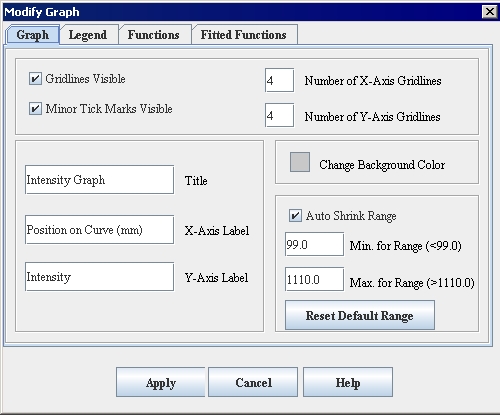
You can adjust the appearance of graphs to interpret the information more clearly or easily. To customize graphs, you use the Modify Graph dialog box , which is accessible through Views > Modify Graph Features in both the Contour VOI window and the Intensity Graph window. The Modify Graph dialog box includes the following four tabbed pages:
- Graph tab, which allows you to show or hide the gridlines and tick marks, change the number of gridlines and background color of the graph, change the labels on the graph, and change the range values.
- Legend tab, which lets you determine whether a legend should appear on the graph and allows you to assign a specific name to each function.
- Functions tab , which allows you to change the appearance of the functions in the graph.
- Fitted Functions tab, which allows you to modify the functions.
|
Graph tab
| ||
|
Gridlines visible
|
Displays, if selected, gridlines on the graph in the Intensity Graph window.
|
|
|
Minor tick marks visible
|
Displays, if selected, the tick marks on the X and Y axes of the graph in the Intensity Graph window.
| |
|
Number of X-axis gridlines
|
Indicates the number of gridlines that appear on the X axis of the graph. The default number of gridlines is 4. You can specify from 1 to 50 gridlines.
| |
|
Number of Y-axis gridlines
|
Indicates the number of gridlines that display on the Y axis of the graph. The default number of gridlines is 4. You can specify from 1 to 50 gridlines.
| |
|
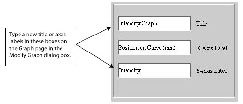
Title
|
Specifies the name of the graph. By default, the name is Intensity Graph. However, you can replace this name with any name you choose.
| |
|
X axis label
|
Specifies the name that appears for the X axis. By default, the name is Position on curve (mm).
| |
|
Y axis label
|
Specifies the name that appears for the Y axis. By default, the name is Intensity.
| |
|
Change background color
|
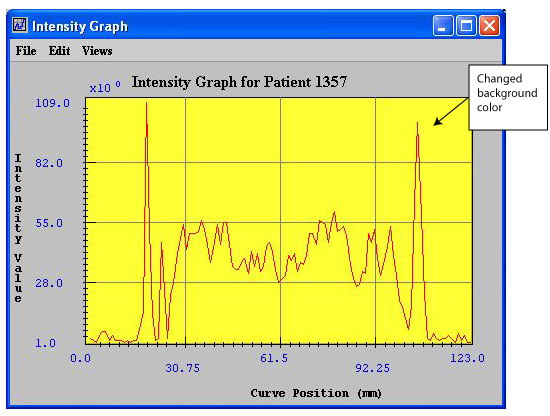
Allows you to choose the color of the background of the graph. When you select this icon, the Pick Background Color dialog box opens. By default, the background color for graphs is light gray. The HSB values are 0 hue, 0 saturation, and 100 brightness and the RGB values are 255 red, green, and blue.
| |
|
Auto Shrink Range
|
Check/uncheck this box to expand or shrink the graph.
| |
|
Min. for range
|
The default minimum range is 207,437.0. If you specify another range, it must be less than the default range.
| |
|
Max for range
|
The default maximum range is 595,910.0. If you specify another range, it must be more than the default range.
| |
|
Reset default range
|
Erases the current minimum and maximum ranges and replaces the values with the default minimum and maximum ranges.
| |
|
Apply
|
Applies the changes you made in this dialog box.
| |
|
Cancel
|
Disregards any changes you made in this dialog box, closes the dialog box, and does not change the threshold.
| |
|
Help
|
Displays online help for this dialog box.
| |
To display or hide the points, or tick marks, on graphs
1 Open an image.
2 Delineate a VOI on the image.
3 Generate an intensity profile (refer to "Generating graphs" ). Either the Contour VOI Graph window or the Intensity Graph window opens.
4 Select Views > Modify Graph Features in either the Contour VOI Graph window or the Intensity Graph window. The Graph page of the Modify Graph dialog box appears.
5 Do one of the following:
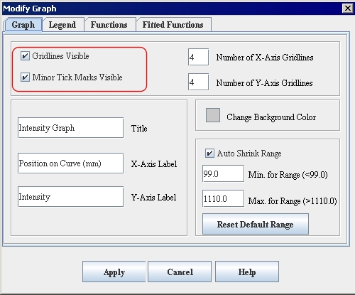
If you want to make the points appear on the graph, select Minor tick marks visible. A check mark appears in the check box.
If you want to make the points invisible, clear Minor tick marks visible.
6 Click Apply.
If you selected Minor tick marks visible, the tick marks along the X and Y axes in the graph appear.
If you cleared Minor tick marks visible, the tick marks disappear from the graph.
7 Do one of the following:
- Close the Modify Graph dialog box.
- Keep the Modify Graph dialog box open to continue modifying the graph.
To display or hide the gridlines on graphs
1 Open an image.
2 Delineate a VOI on the image.
3 Generate an intensity profile (refer to "Generating graphs"). Either the Contour VOI Graph window (Figure 10) or the Intensity Graph window (Figure 11) opens.
4 Select Views > Modify Graph Features in either Contour VOI Graph window or the Intensity Graph window. The Graph page of the Modify Graph dialog box (Figure 13) appears.
5 Do one of the following:
- To make the gridlines appear on the graph, select, if not already selected, Gridlines visible. A check mark appears in the check box.
- To make the gridlines disappear from the graph, clear Gridlines visible. The check box is empty.
6 Click Apply.
If you selected Gridlines visible, horizontal and vertical gridlines appear in the graph.
If you cleared the check box, the gridlines disappear from the graph.
7 Do one of the following:
- Close the Modify Graph dialog box.
- Keep the Modify Graph dialog box open to continue modifying the graph.
To change the number of gridlines in graphs
1 Select Views > Modify Graph Features in either the Contour VOI Graph window (Figure 10) or the Intensity Graph window (Figure 11). The Graph page of the Modify Graph dialog box (Figure 13) appears.
2 Change the number of X -axis gridlines in Number of X -axis gridlines (Figure 15) by specifying a value from 1 to 50. The default number of gridlines is 4.
3 Change the number of Y -axis gridlines in Number of Y -axis gridlines (Figure 15) by specifying a value from 1 to 50. The default number of gridlines is 4.
4 Click Apply.
The number of horizontal and vertical gridlines that you specified appear in the graph in the Intensity Graph window.
Tip: If you specify many gridlines, to see the gridlines more clearly, resize the Modify Graph dialog box.
5 Do one of the following:
- Close the Modify Graph dialog box.
- Keep the Modify Graph dialog box open to continue modifying the graph.
To change the graph title and labels on the X and Y axes
1 Open an image.
2 Delineate a VOI on the image.
3 Generate an intensity profile (refer to "Generating graphs". Either the Contour VOI Graph window or the Intensity Graph window opens.
4 Select Views > Modify Graph Features in Contour VOI Graph window or the Intensity Graph window. The Graph page of the Modify Graph dialog box appears.
5 Type the new title and axes labels in Title, X-axis label, and Y -axis label boxes (Figure 16).
6 Click Apply.
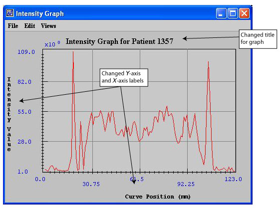
The new title appears number of horizontal and vertical gridlines that you specified now appear in the graph (Figure 17).
Tip: If you specify many gridlines, you might want to resize the Modify Graph dialog box to see the gridlines more clearly.
7 Do one of the following:
- Close the Modify Graph dialog box.
- Keep the Modify Graph dialog box open to continue modifying the graph.
To change the background color of graphs
1 Open an image.
2 Delineate a VOI on the image.
3 Generate an intensity profile (refer to "Generating graphs"). Either the Contour VOI Graph window or the Intensity Graph window opens.
4 Select Views > Modify Graph Features in either the Contour VOI Graph window or the Intensity Graph window. The Graph page of the Modify Graph dialog box (Figure 13) appears.
5 Select Change background color.
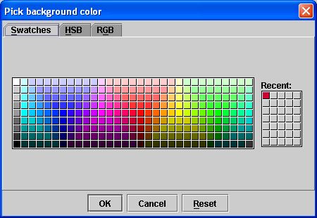
The Pick Background Color dialog box (Figure 19) opens.
6 Select a color from one of the three pages in this dialog box. Refer to "To change background and border colors" for information on how to select a color. Refer to "To change background and border colors" for information on how to select a color.
7 Click OK to apply the color to the graph background. The Pick Background Color dialog box closes, and the graph background (Figure 20) changes to the color you selected.
To reset graphs to their original background colors
To return either the intensity graph or the contour VOI graph back to its default colors, select Views > Reset Graph to Original or press Ctrl Z in either the Contour VOI Graph window or Intensity Graph window as appropriate.
