Cost functions used in MIPAV algorithms and Creating a mask using the Paint Grow Segmentation method: Difference between pages
m (1 revision imported) |
m (1 revision imported) |
||
| Line 1: | Line 1: | ||
You can create a mask using the paint grow segmentation method, which uses voxel aggregation to group voxels into larger regions. You begin by selecting a voxel to serve as the ''seed point,'' or starting point. The software applies paint color to all voxels touching the seed point that fall within the intensity range that you specify.<br />'''Note:''' You cannot apply the paint grow segmentation method to RGB images.<br /> | |||
==== To create a mask using the Paint Grow tool ==== | |||
[[Image:FillsAreaIco.jpg]] - Fill an Area with Desired Color<br /> | |||
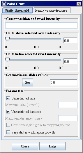
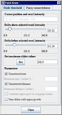
1 Click the Fill an Area with Desired Color icon. The Paint Grow dialog box appears (Figure 9).<br /> | |||
2 Select the seed point, which is used as a starting point for the paint grow operation. To do this, move the pointer to the image. As you move the cursor, the location and intensity of the voxel under the pointer tip appears in the Cursor position and voxel intensity text box. Click the voxel you want to designate as the seed point.<br /> | |||
3 Adjust the delta values and parameters. <br /> | |||
4 Click Apply when complete to begin the paint grow method. The Paint Grow dialog box closes.<br />''' To correct the mask<br /></font>'''</div> | |||
If the results are not what you want, do the following: | |||
1 Click the Paint Grow button. The Paint Grow dialog box appears.<br /> | |||
2 Select the seed point, which is used as a starting point for the paint grow operation. To do this, move the pointer to the image. As you move the cursor, the location and intensity of the voxel under the pointer tip appears in the Cursor position and voxel intensity text box. Click the voxel you want to designate as the seed point.<br /> | |||
3 Adjust the delta values and parameters. <br /> | |||
4 Click Apply when complete to begin the paint grow method. The Paint Grow dialog box closes.<br /> | |||
If the results are not what you want, do either of the following:<br /> | |||
Click the Undo last region paint icon, and start again.<br /> | |||
Click the Erase icon, or click, the Erase all paint icon, to erase all paint.<br /> | |||
'''To commit the mask'''<br /> | |||
</ | |||
Click one of the following commit buttons: | |||
[[Image:MasksInsidePaintedAreaIco.jpg]] - the Masks Inside Painted Area icon.<br />[[Image:MasksOutsidePaintedAreaIco.jpg]] - the Masks Outside Painted Area icon.<br /> | |||
==== Paint Grow dialog box options ==== | |||
== | {| border="1" cellpadding="5" | ||
|+ '''Figure 9. Paint Grow dialog box ''' | |||
|- | |||
| | |||
<div class="CellBody"><span style="font-style: normal; text-decoration: none; text-transform: none; vertical-align: baseline">'''<font color="#000000">Cursor position and voxel intensity</font>'''</span></div> | |||
| | |||
<div class="CellBody">Indicates the coordinates and intensity of the pixel under the mouse pointer tip. This pixel is the seed point.</div> | |||
| rowspan="3" colspan="1" | | |||
[[Image:PaintGrow_StaticThreshold.jpg]] | |||
|- | |||
| | |||
<div class="CellBody"><span style="font-style: normal; text-decoration: none; text-transform: none; vertical-align: baseline">'''<font color="#000000">Delta above selected voxel intensity</font>'''</span></div> | |||
| | |||
<div class="CellBody">Once a seed point has been selected, MIPAV uses this value to determine whether to fill adjacent voxels with color. The voxels that are filled must have intensity levels that fall within the range of the seed point intensity minus the lower delta value and the upper delta value. For example, if seed point has an intensity of 100.0, and the <span style="font-weight: normal; text-decoration: none; text-transform: none; vertical-align: baseline">''<font color="#000000">Delta Above Selected Pixel Intensity </font>''</span>value is 10 and the <span style="font-weight: normal; text-decoration: none; text-transform: none; vertical-align: baseline">''<font color="#000000">Delta Below Selected Pixel Intensity </font>''</span>value is 15, MIPAV color-fills adjacent voxels whose intensities range from 85.0 to 110.0.</div> | |||
|- | |||
| | |||
<div class="CellBody"><span style="font-style: normal; text-decoration: none; text-transform: none; vertical-align: baseline">'''<font color="#000000">Delta below selected voxel intensity</font>'''</span></div> | |||
| | |||
<div class="CellBody">Once a seed point is, MIPAV uses this value to determine whether to fill adjacent voxels with color. The voxels that are filled must have intensity levels that fall within the range of the seed point intensity minus the lower delta value and the upper delta value.</div> | |||
|- | |||
| rowspan="1" colspan="1" | | |||
<div class="CellBody"><span style="font-style: normal; text-decoration: none; text-transform: none; vertical-align: baseline">'''<font color="#000000">Parameters:</font>'''</span></div> <div class="CellBody"><span style="font-style: normal; text-decoration: none; text-transform: none; vertical-align: baseline">'''<font color="#000000">Unrestricted size</font>'''</span></div> <div class="CellBody"><span style="font-style: normal; text-decoration: none; text-transform: none; vertical-align: baseline">'''<font color="#000000">Maximum size</font>'''</span></div> <div class="CellBody"><span style="font-style: normal; text-decoration: none; text-transform: none; vertical-align: baseline">'''<font color="#000000">Unrestricted distance</font>'''</span></div> <div class="CellBody"><span style="font-style: normal; text-decoration: none; text-transform: none; vertical-align: baseline">'''<font color="#000000">Maximum distance</font>'''</span></div> | |||
| rowspan="1" colspan="2" | | |||
<div class="CellBody">Constrains the growth of the paint grow operation. Select the <span style="font-style: normal; text-decoration: none; text-transform: none; vertical-align: baseline">'''<font color="#000000">Unrestricted size</font>'''</span> and <span style="font-style: normal; text-decoration: none; text-transform: none; vertical-align: baseline">'''<font color="#000000">Unrestricted distance</font>'''</span> check boxes to allow the paint grow operation to be applied without restraint. If the <span style="font-style: normal; text-decoration: none; text-transform: none; vertical-align: baseline">'''<font color="#000000">Unrestricted size</font>'''</span> check box is not selected, type the <span style="font-style: normal; text-decoration: none; text-transform: none; vertical-align: baseline">'''<font color="#000000">maximum size</font>'''</span> (in cubic meters) of the paint grow region in the text box. If the <span style="font-style: normal; text-decoration: none; text-transform: none; vertical-align: baseline">'''<font color="#000000">Unrestricted distance</font>'''</span> check box is not selected, type the maximum distance from the original seed point in the text box.</div> | |||
|- | |||
| rowspan="1" colspan="3" | | |||
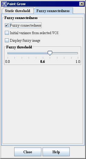
<div class="CellBody"><span style="font-style: normal; text-decoration: none; text-transform: none; vertical-align: baseline">'''<font color="#000000">Fuzzy connectedness</font>'''</span></div> | |||
|- | |||
| | |||
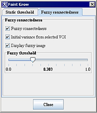
<div class="CellBody"><span style="font-style: normal; text-decoration: none; text-transform: none; vertical-align: baseline">'''<font color="#000000">Fuzzy connectedness</font>'''</span></div> | |||
| rowspan="1" colspan="2" | | |||
<div class="CellBody">Check tis box to use the fuzzy connectedness coefficient instead of static threshold. Here, Fuzzy connectedness represents the idea of connection or "hanging-togetherness" of image elements in an object by assigning a strength of connectedness to every possible path between every possible pair of image elements. </div> <div class="CellBody">A fuzzy connected object is defined with a fuzzy threshold or the strength of connectedness. </div> | |||
|- | |||
| | |||
<div class="CellBody"><span style="font-style: normal; text-decoration: none; text-transform: none; vertical-align: baseline">'''<font color="#000000">Initial variance from selected VOI</font>'''</span></div> | |||
| | |||
<div class="CellBody">Uses the initial intensity values from the selected region of interest (VOI).</div> | |||
| rowspan="6" colspan="1" | | |||
[[Image:PaintGrow_FuzzyConnectedness.jpg]] | |||
|- | |||
| | |||
<div class="CellBody"><span style="font-style: normal; text-decoration: none; text-transform: none; vertical-align: baseline">'''<font color="#000000">Display fuzzy image</font>'''</span></div> | |||
| | |||
<div class="CellBody">Displays the result image in a separate frame. </div> | |||
|- | |||
| | |||
<div class="CellBody"><span style="font-style: normal; text-decoration: none; text-transform: none; vertical-align: baseline">'''<font color="#000000">Fuzzy threshold</font>'''</span></div> | |||
| | |||
<div class="CellBody">is a threshold on the strength of connectedness of image elements.</div> | |||
|- | |||
| | |||
<div class="CellBody"><span style="font-style: normal; text-decoration: none; text-transform: none; vertical-align: baseline">'''<font color="#000000">Close</font>'''</span></div> | |||
| | |||
<div class="CellBody">Closes this dialog box.</div> | |||
|- | |||
| | |||
<div class="CellBody"><span style="font-style: normal; text-decoration: none; text-transform: none; vertical-align: baseline">'''<font color="#000000">Cancel</font>'''</span></div> | |||
| | |||
<div class="CellBody">Disregards any changes that you made in this dialog box and closes the dialog box.</div> | |||
|- | |||
| | |||
<div class="CellBody"><span style="font-style: normal; text-decoration: none; text-transform: none; vertical-align: baseline">'''<font color="#000000">Help</font>'''</span></div> | |||
| | |||
<div class="CellBody">Displays online help for this dialog box.</div> | |||
|} | |||
==== Examples of using the Paint Grow tool ==== | |||
< | Here, is a step-by-step guide for selecting a region(s) of interest using the Paint Grow tool options. In this example we will use an image of the human eye and we will try to segment the blood vessels located on the retina. | ||
First, make sure to adjust the contrast of your image so that the different tissues appear visually distinctive. For images with more than 8 bits per voxel you may want to use the various LUT available in MIPAV.<br /> | |||
'''To segment blood vessels using the static threshold'''<br /> | |||
1 Open the Paint Grow dialog box.<br /> | |||
2 Use the mouse cursor to select the point on the image (on a blood vessel) which has the desired intensity value.<br /> | |||
3 Use the Change Paint Color option to select the color (other than red) which will be used for painting.<br /> | |||
4 On the Static Threshold tab, adjust the intensity thresholds so that the tissue you want to preserve is highlighted.<br />5 Check the Unrestricted size and Unrestricted distance options. This will allow the paint grow operation to be applied without restriction.<br />6 Watch the paint region growing.<br /> | |||
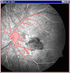
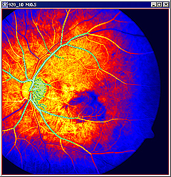
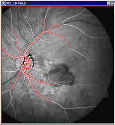
For example, when selecting the blood vessels, the image might look like the panel A for grayscale images or panel B for images after applying Blue LUT in the Figure 10 below. | |||
{| border="1" cellpadding="5" | |||
|+ '''Figure 10. The Paint Grow tool was used to locate the blood vessels on the grayscale image (A) first, and then on the same image after applying the Blue LUT (B). ''' | |||
|- | |||
| | |||
[[Image:RetinaVesselsGrayscale.jpg]] | |||
|<div class="CellBody">A - the painted region appears in red (which is the default color)</div> | |||
|- | |||
| | |||
[[Image:RetinaVessels BlueLUT.jpg]] | |||
|<div class="CellBody">B - the painted region appears in green, because we selected it as a color contrast to LUT colors</div> | |||
|[[Image:RetinaVeselsDialogOptions.jpg]] | |||
|Dialog Options box | |||
|} | |||
'''To segment blood vessels using the Fuzzy Connectedness option'''<br /> | |||
1 Open an image of interest.<br /> | |||
2 You might consider to delineate a VOI on a region of the image which is of your interest, first. This is optional.<br /> | |||
1 Open the Paint Grow dialog box, and then open the Fuzzy Connectedness tab.<br /> | |||
2 Check the '''Fuzzy Connectedness''' check box to activate the tool.<br /> | |||
3 Check the '''Initial variance from selected VOI''' box (optional).<br /> | |||
4 Check the '''Display fuzzy image option''' to view the result in a new frame.<br /> | |||
5 Use the mouse cursor to select the point on the image (on a blood vessel) which has the desired intensity value.<br /> | |||
6 Adjust the Fuzzy thresholds so that the tissue you want to preserve is highlighted.<br /> | |||
7 Watch the paint region appeared in a new frame.<br /> | |||
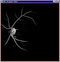
For example, when selecting the blood vessels, the image might look like the panel A or panel B for images in the Figure 11 below. | |||
== | {| border="1" cellpadding="5" | ||
|+ '''Figure 11. The Fuzzy Connectedness option.''' | |||
|- | |||
| | |||
[[Image:RetinaVesselsFuzzyGrayscale.jpg]] | |||
|<div class="CellBody">a - the painted region appears in red </div> | |||
|- | |||
| | |||
[[Image:RetinaVesselsFuzzyResult.jpg]] | |||
|<div class="CellBody">b -the painted region also appears in a new frame</div> | |||
|- | |||
| | |||
[[Image:RetinaVeselsDialogOptionsFuzzy.jpg]] | |||
|<div class="CellBody">c</div> | |||
|} | |||
[[Segmenting Images Using Contours and Masks:Converting VOI contours to masks]] | |||
Latest revision as of 16:28, 9 February 2024
You can create a mask using the paint grow segmentation method, which uses voxel aggregation to group voxels into larger regions. You begin by selecting a voxel to serve as the seed point, or starting point. The software applies paint color to all voxels touching the seed point that fall within the intensity range that you specify.
Note: You cannot apply the paint grow segmentation method to RGB images.
To create a mask using the Paint Grow tool
![]() - Fill an Area with Desired Color
- Fill an Area with Desired Color
1 Click the Fill an Area with Desired Color icon. The Paint Grow dialog box appears (Figure 9).
2 Select the seed point, which is used as a starting point for the paint grow operation. To do this, move the pointer to the image. As you move the cursor, the location and intensity of the voxel under the pointer tip appears in the Cursor position and voxel intensity text box. Click the voxel you want to designate as the seed point.
3 Adjust the delta values and parameters.
4 Click Apply when complete to begin the paint grow method. The Paint Grow dialog box closes.
To correct the mask
If the results are not what you want, do the following:
1 Click the Paint Grow button. The Paint Grow dialog box appears.
2 Select the seed point, which is used as a starting point for the paint grow operation. To do this, move the pointer to the image. As you move the cursor, the location and intensity of the voxel under the pointer tip appears in the Cursor position and voxel intensity text box. Click the voxel you want to designate as the seed point.
3 Adjust the delta values and parameters.
4 Click Apply when complete to begin the paint grow method. The Paint Grow dialog box closes.
If the results are not what you want, do either of the following:
Click the Undo last region paint icon, and start again.
Click the Erase icon, or click, the Erase all paint icon, to erase all paint.
To commit the mask
Click one of the following commit buttons:
![]() - the Masks Inside Painted Area icon.
- the Masks Inside Painted Area icon.![]() - the Masks Outside Painted Area icon.
- the Masks Outside Painted Area icon.
Paint Grow dialog box options
|
Cursor position and voxel intensity
|
Indicates the coordinates and intensity of the pixel under the mouse pointer tip. This pixel is the seed point.
|
|
|
Delta above selected voxel intensity
|
Once a seed point has been selected, MIPAV uses this value to determine whether to fill adjacent voxels with color. The voxels that are filled must have intensity levels that fall within the range of the seed point intensity minus the lower delta value and the upper delta value. For example, if seed point has an intensity of 100.0, and the Delta Above Selected Pixel Intensity value is 10 and the Delta Below Selected Pixel Intensity value is 15, MIPAV color-fills adjacent voxels whose intensities range from 85.0 to 110.0.
| |
|
Delta below selected voxel intensity
|
Once a seed point is, MIPAV uses this value to determine whether to fill adjacent voxels with color. The voxels that are filled must have intensity levels that fall within the range of the seed point intensity minus the lower delta value and the upper delta value.
| |
|
Parameters: Unrestricted size Maximum size Unrestricted distance Maximum distance
|
Constrains the growth of the paint grow operation. Select the Unrestricted size and Unrestricted distance check boxes to allow the paint grow operation to be applied without restraint. If the Unrestricted size check box is not selected, type the maximum size (in cubic meters) of the paint grow region in the text box. If the Unrestricted distance check box is not selected, type the maximum distance from the original seed point in the text box.
| |
|
Fuzzy connectedness
| ||
|
Fuzzy connectedness
|
Check tis box to use the fuzzy connectedness coefficient instead of static threshold. Here, Fuzzy connectedness represents the idea of connection or "hanging-togetherness" of image elements in an object by assigning a strength of connectedness to every possible path between every possible pair of image elements. A fuzzy connected object is defined with a fuzzy threshold or the strength of connectedness.
| |
|
Initial variance from selected VOI
|
Uses the initial intensity values from the selected region of interest (VOI).
|
|
|
Display fuzzy image
|
Displays the result image in a separate frame.
| |
|
Fuzzy threshold
|
is a threshold on the strength of connectedness of image elements.
| |
|
Close
|
Closes this dialog box.
| |
|
Cancel
|
Disregards any changes that you made in this dialog box and closes the dialog box.
| |
|
Help
|
Displays online help for this dialog box.
| |
Examples of using the Paint Grow tool
Here, is a step-by-step guide for selecting a region(s) of interest using the Paint Grow tool options. In this example we will use an image of the human eye and we will try to segment the blood vessels located on the retina.
First, make sure to adjust the contrast of your image so that the different tissues appear visually distinctive. For images with more than 8 bits per voxel you may want to use the various LUT available in MIPAV.
To segment blood vessels using the static threshold
1 Open the Paint Grow dialog box.
2 Use the mouse cursor to select the point on the image (on a blood vessel) which has the desired intensity value.
3 Use the Change Paint Color option to select the color (other than red) which will be used for painting.
4 On the Static Threshold tab, adjust the intensity thresholds so that the tissue you want to preserve is highlighted.
5 Check the Unrestricted size and Unrestricted distance options. This will allow the paint grow operation to be applied without restriction.
6 Watch the paint region growing.
For example, when selecting the blood vessels, the image might look like the panel A for grayscale images or panel B for images after applying Blue LUT in the Figure 10 below.
To segment blood vessels using the Fuzzy Connectedness option
1 Open an image of interest.
2 You might consider to delineate a VOI on a region of the image which is of your interest, first. This is optional.
1 Open the Paint Grow dialog box, and then open the Fuzzy Connectedness tab.
2 Check the Fuzzy Connectedness check box to activate the tool.
3 Check the Initial variance from selected VOI box (optional).
4 Check the Display fuzzy image option to view the result in a new frame.
5 Use the mouse cursor to select the point on the image (on a blood vessel) which has the desired intensity value.
6 Adjust the Fuzzy thresholds so that the tissue you want to preserve is highlighted.
7 Watch the paint region appeared in a new frame.
For example, when selecting the blood vessels, the image might look like the panel A or panel B for images in the Figure 11 below.
a - the painted region appears in red
| |
b -the painted region also appears in a new frame
| |
c
|
Segmenting Images Using Contours and Masks:Converting VOI contours to masks
