Extract Brain: Extract Brain Surface (BSE) and Extract Surface (Marching Cubes): Difference between pages
m (1 revision imported) |
MIPAV>Olgavovk mNo edit summary |
||
| Line 1: | Line 1: | ||
''The Extract Surface algorithm described in this section is based on the Marching Cubes algorithm, which was designed by William E. Lorensen and Harvey E. Cline to extract surface information from a 3D array of values. The applications of this algorithm are mainly concerned with medical visualizations such as CT and MRI scan data images.'' | |||
=== Background === | === Background === | ||
The basic notion of the algorithm is that we can define a voxel by the pixel values at the eight corners of the cube. We also can define an isosurface which intersects the cube, refer to Figures 1 and 2. If one or more pixels of a voxel have values less than the user-specified isovalue, and one or more have values greater than this value, we know that the voxel must contribute some component of the isosurface. | |||
By determining which edges of the voxel are intersected by the isosurface, we can create triangular patches that divide the voxel between regions ''within the isosurface'' and regions ''outside''. By connecting the patches from all voxel on the isosurface boundary, we get a surface representation. | |||
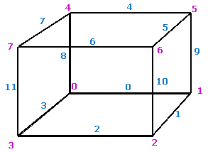
The indexing convention for vertices and edges used in the algorithm is shown in Figure 1 below. | |||
<div> | |||
== | {| border="1" cellpadding="5" | ||
|+ <div>'''Figure 1. The indexing convention for vertices and edges. Here, edge indexes are shown in ''blue'' and vertex indexes are shown in ''magenta''''' </div> | |||
|- | |||
| | |||
<div style="font-style: normal; font-weight: normal; margin-bottom: 0pt; margin-left: 0pt; margin-right: 0pt; margin-top: 1pt; text-align: left; text-decoration: none; text-indent: 0pt; text-transform: none; vertical-align: baseline"><font size="2pt"><font color="#000000"><div><center>[[Image:EdgeIndex_VertexIndex.png]]</center></div><br /> </font></font></div> | |||
|} | |||
</div> | |||
==== | {| width="90%" border="1" frame="hsides" frame="hsides" | ||
|- | |||
| width="9%" valign="top" | | |||
[[Image:exampleicon.gif]] | |||
| width="81%" bgcolor="#B0E0E6" | | |||
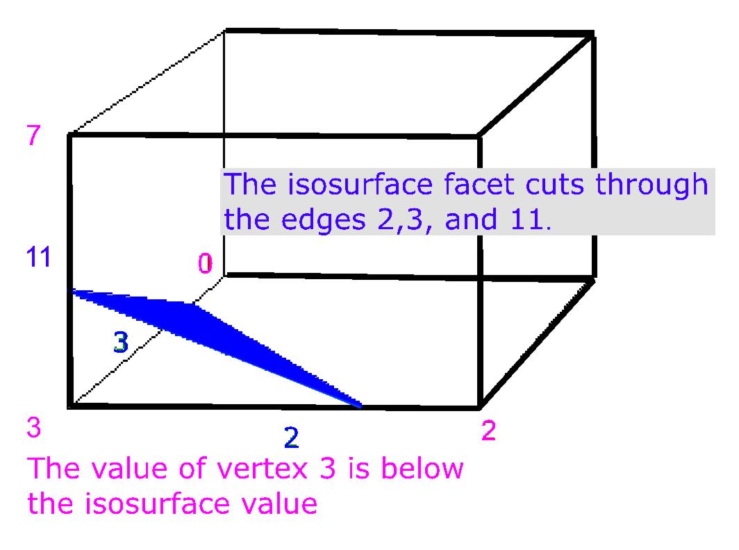
'''Example:''' If for example, the value at vertex 3 is below the isosurface value and all the values of all the other vertices are above the isosurface value, then we would create a triangular facet which cuts through edges 2,3, and 11 as shown in Figure 2. The exact position of the vertices of the triangular facet depends on the relationship of the isosurface value to the values at the vertices 3-2, 3-0, 3-7 respectively. | |||
|} | |||
<br /><div> | |||
==== | {| border="1" cellpadding="5" | ||
|+ <div>'''Figure 2. Vertex 3 is inside the volume''' </div> | |||
|- | |||
| | |||
<div style="font-style: normal; font-weight: normal; margin-bottom: 0pt; margin-left: 0pt; margin-right: 0pt; margin-top: 1pt; text-align: left; text-decoration: none; text-indent: 0pt; text-transform: none; vertical-align: baseline"><font size="2pt"><font color="#000000"><div align="left">[[Image:MarchingCubesFigure26.jpg]]</div><br /> </font></font></div> | |||
|} | |||
</div> | |||
Therefore, we must specify a ''threshold value'', first. For this value, some voxels will be entirely ''inside'' or ''outside'' the corresponding isosurface and some voxels will be ''intersected by the isosurface''. In the first pass of the algorithm, the ''voxels that are intersected by the threshold value'' are identified. In the second pass, these voxels are examined and a set of one or more polygons is produced. These polygons are then output for rendering. | |||
= | Each of the voxel's 8 vertices can be either inside or outside of the isosurface value, thus, there are ''2''''8'''' = 256 ''possible ways how an isosurface can intersect the voxel. To simplify the algorithm, we can reduce this complexity by assuming that cell combinations are duplicated under the following conditions: | ||
* Rotating by any degree over any of the 3 primary axis (X,Y, or Z); | |||
* Mirroring the isosurface's shape across any of the 3 primary axis; | |||
* Inverting all corners and flipping the normals of the relating polygons. | |||
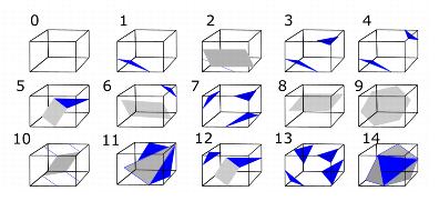
By taking this symmetry into account, we can reduce the original 256 combinations to a total of 15 combinations, refer to Figure 3. | |||
{| border="1" cellpadding="5" | |||
|+ <div>'''Figure 3. How 256 cases can be reduced to 15 cases''' </div> | |||
{| | |||
|- | |- | ||
| | | | ||
<div style="font-style: normal; font-weight: normal; margin-bottom: 0pt; margin-left: 0pt; margin-right: 0pt; margin-top: 1pt; text-align: left; text-decoration: none; text-indent: 0pt; text-transform: none; vertical-align: baseline"><font size="2pt"><font color="#000000"><div align="left">[[Image:MarchingCubes8.jpg]]</div><br /> </font></font></div> | |||
|} | |} | ||
Now we can use a table (called ''edgeTable'') which maps the vertices under the isosurface to the intersecting edges. An 8 bit index can be formed from the table where each bit corresponds to a vertex, refer to [MarchingCubes.html#wp1780799 Table 1]. | |||
<div>'''Table 1. edgeTable''' </div><div> cubeindex = 0; </div><div> if (grid.val[0] < isolevel) cubeindex |= 1; </div><div> if (grid.val[1] < isolevel) cubeindex |= 2; </div><div> if (grid.val[2] < isolevel) cubeindex |= 4; </div><div> if (grid.val[3] < isolevel) cubeindex |= 8; </div><div> if (grid.val[4] < isolevel) cubeindex |= 16; </div><div> if (grid.val[5] < isolevel) cubeindex |= 32; </div><div> if (grid.val[6] < isolevel) cubeindex |= 64; </div><div> if (grid.val[7] < isolevel) cubeindex |= 128; </div> | |||
Looking up the edgeTable returns a 12 bit number, each bit corresponding to an edge. 0 if the edge isn't cut by the isosurface and 1 if the edge is cut by the isosurface. If none of the edges are cut the table returns zero. This occurs when the cubeindex is ''0'', which means that all vertices are below the isosurface, or ''0xff ''(all vertices above the isosurface). | |||
Using the example shown in Figure 1, where only vertex 3 was below the isosurface, cubeindex would equal 0000 1000 or 8. The edgeTable{8} equals 1000 0000 1100. This means that edge 2,3, and 11 are intersected by the isosurface, refer to Figure 2. | |||
Now the intersection points can be calculated by linear interpolation. If P''1'' and P''2'' are the vertices of a cut edge and V''1'' and V''2'' are the scalar values of each vertex, the intersection point P is given by the following equation: | |||
[[Image:MarchingCubes12.jpg]] | |||
The last part of the algorithm involves forming the correct triangular facets from the positions where the isosurface intersects the edges of the grid cell. In order to do that, another table (also called ''triTable'') is used. This table uses the same cubeindex from edgeTable, but allows the vertex sequence to be searched for as many triangular facets as necessary to represent the isosurface within the grid cell. Each of the non-trivial configurations results in between 1 and 4 triangles is added to the isosurface. The actual vertices themselves can be computed either by interpolating along the edges, or, by default their location to the middle of the edge. | |||
Since we can create surface patches for a single voxel, we can apply this algorithm to the entire volume.We can either treat each cube independently, or we can propagate edge intersections between the cubes which share the edges. The sharing of edge/vertex information also results in a more compact model. | |||
==== References ==== | ==== References ==== | ||
The following sources were used: | |||
Lorensen, W.E. and Cline, H.E., ''Marching Cubes: a high resolution 3D surface reconstruction algorithm'', Computer Graphics, Vol. 21, No. 4, pp 163-169 (Proc. of SIGGRAPH), 1987. | |||
Paul Bourke, ''Polygonising a scalar field Also known as: "3D Contouring," "Marching Cubes," "Surface Reconstruction;" ''May 1994, http://local.wasp.uwa.edu.au/~pbourke/modelling/polygonise/ | |||
==== Image types ==== | |||
You can apply the Extract Surface algorithm to any type of images using in MIPAV. | |||
=== Output Files === | |||
The output of the algorithm is a set of vertices and normals as well as the map that shows how the vertices are connected. This information can be saved in following formats: | |||
** Tab-delimited (*.txt); | |||
** Surface (*.sur), which is MIPAV format. A surface file contains the above information plus the additional information that describes the surface color and more. This is defined by an XML scheme, which can be found on the MIPAV web site (''http://mipav.cit.nih.gov/documentation/xml-format/image/''); | |||
** VRML (*.wrl), which can then be processed by any application that can read and display VRML objects. | |||
=== Applying the Extract Surface Algorithm === | |||
=== | ===== To run the algorithm, complete the following steps: ===== | ||
# Open an image of interest; | |||
# Select Algorithms > Extract Surface (marching cubes); | |||
# The Extract Surface dialog box opens. Here, you can choose to apply following three options: | |||
#* You may select a VOI region, and then apply the algorithm to the selected VOI; | |||
#* You may apply a mask to the image first, and then run the algorithm; | |||
#* Or you may extract a surface from the region with a chosen intensity level. | |||
# Select a type and location of the output file. You can save the result as a *.txt file (in Tab-delimited format), *.wrl file, or surface file (*.sur). Refer to Section [MarchingCubes.html#wp1785344 "Output Files"]for more information. | |||
# Press OK. | |||
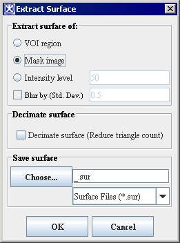
The algorithm begins to run, and a progress bar appears with the status. When the algorithm finishes running, the progress bar disappears, and the results appear as a file in selected format in a chosen location. For more information about the dialog box options, refer to Figure 4.'' '' | |||
<div> | <div>'''Figure 4. The Extract Surface dialog box options''' </div> | ||
{| border="1" cellpadding="5" | {| border="1" cellpadding="5" | ||
|+ | |+ | ||
|- | |- | ||
| | | | ||
<div> | <div>'''VOI Region''' </div> | ||
| | | | ||
| rowspan=" | <div>Applies the algorithm to the volume delineated by the VOI. </div> | ||
<div><div><center>[[Image: | | rowspan="7" colspan="1" | | ||
<div><div><center>[[Image:ExtractSurfaceDialog.png]]</center></div> </div><div> </div><div> </div><div> </div><div> </div><div> </div><div> </div><div> </div><div> </div><div> </div> | |||
|- | |- | ||
| | | | ||
<div>''' | <div>'''Mask Image''' </div> | ||
| | | | ||
<div> | <div>Applies the algorithm to the volume within a chosen mask. You must apply the mask, first. </div> | ||
|- | |- | ||
| | | | ||
<div>''' | <div>'''Intensity Level''' </div> | ||
| | | | ||
<div> | <div>Applies the algorithm to the region with the chosen intensity level. By default, the intensity level value is set to 50. </div> | ||
|- | |- | ||
| | | | ||
<div> | <div>Blur by (Std.Dev.) </div> | ||
| | |||
<div>Blurs the image to improve the extracted surface. The value specifies the standard deviation of the Gaussian filter used to regularize the image. </div> | |||
|- | |- | ||
| | | | ||
<div>''' | <div>'''Decimate Surface''' </div> | ||
| | |||
<div> | <div>If selected, reduces the count of triangle facets, which results the more compact algorithm. </div> | ||
|- | |- | ||
| | | | ||
<div>''' | <div>'''Choose''' </div> | ||
| | |||
<div> | <div>Use this button to select a catalogue where you would like to store your results and choose a file format (*.txt, *.sur, or *.wrl). </div> | ||
|- | |- | ||
| | | | ||
<div>''' | <div>'''OK''' </div> | ||
| | | | ||
<div>Applies the algorithm according to the specifications in this dialog box. </div> | |||
<div>Applies the algorithm to | |||
|- | |- | ||
| | | | ||
<div>''' | <div>'''Cancel''' </div> | ||
| rowspan="1" colspan="2" | | | rowspan="1" colspan="2" | | ||
<div> | <div>Disregards any changes that you made in this dialog box and closes it. </div> | ||
|- | |- | ||
| | | | ||
<div>''' | <div>'''Help''' </div> | ||
| rowspan="1" colspan="2" | | | rowspan="1" colspan="2" | | ||
<div> | <div>Displays online help for this dialog box. </div> | ||
|} | |||
| | |||
<div> | |||
==== Examples ==== | |||
'''1. To apply the algorithm to a VOI region:''' | |||
# Open an image of interest. | |||
# Delineate a VOI on the image, and then call the Algorithms> Extract Surface (marching cubes). | |||
# In the Extract Surface dialog box that appears, select the VOI Region option. | |||
# Select the surface file type as an output, and then specify the file name and location. | |||
# Press OK. The algorithm begins to run, and a progress bar appears showing the status. | |||
# When the algorithm finishes running and the progress bar disappears, click the Volume Tri-planar View icon on the MIPAV toolbar. | |||
# The Resample dialog box appears. See Figure 5. | |||
# In the Expected Extents box, specify the value for the Z direction. The value must be in a power of two (32, 64, 128, 256). Refer to Figure 5. The bigger number you choose, the higher resolution you receive.[<sup>1</sup>] | |||
# Press Resample to proceed. | |||
# The 3D viewer opens for the selected image. | |||
# Click the Add Surface to Viewer icon and add the surface file from Step 5 to the Surface list. Then, select the file name and press Add. | |||
# The surface will be added to the image. To adjust the display of the image, use the Surface options, such as color and opacity. Refer to Figure 6. | |||
<div> | |||
{| border="1" cellpadding="5" | |||
|+ <div>'''Figure 5. The Resample dialog''' </div> | |||
|- | |- | ||
| | | | ||
<div> | <div style="font-style: normal; font-weight: normal; margin-bottom: 0pt; margin-left: 0pt; margin-right: 0pt; margin-top: 1pt; text-align: left; text-decoration: none; text-indent: 0pt; text-transform: none; vertical-align: baseline"><font size="2pt"><font color="#000000"><div align="left">[[Image:MarchingCubes4.jpg]]</div><br /> </font></font></div> | ||
|} | |||
<div> | |||
</div> | |||
<div> | |||
{| border="1" cellpadding="5" | |||
|+ <div>'''Figure 6. The view of the surface extracted using the VOI Region option ''' </div> | |||
|- | |- | ||
| | | | ||
<div>Extract | <div style="font-style: normal; font-weight: normal; margin-bottom: 0pt; margin-left: 0pt; margin-right: 0pt; margin-top: 1pt; text-align: left; text-decoration: none; text-indent: 0pt; text-transform: none; vertical-align: baseline"><font size="2pt"><font color="#000000"><div><center>[[Image:MarchCubesVOIExample.png]]</center></div><br /> </font></font></div> | ||
| | |} | ||
<div> | |||
'''2. To use the Mask Image option:''' | |||
# Open an image of interest. | |||
# Create a mask. | |||
# Call the Algorithms> Extract Surface (marching cubes). | |||
# In the dialog box that appears, select the Mask Image option. | |||
# Select the surface file as an output, and then specify the file name and location. Press OK. | |||
# When the algorithm finishes running, click the Volume Tri-planar View icon on the MIPAV toolbar and follow the steps 6--12 from the first example. Refer to Figure 7. | |||
<div> | |||
{| border="1" cellpadding="5" | |||
|+ <div>'''Figure 7. The view of the surface extracted using the Mask Image option''' </div> | |||
|- | |- | ||
| | | | ||
<div>''' | <div style="font-style: normal; font-weight: normal; margin-bottom: 0pt; margin-left: 0pt; margin-right: 0pt; margin-top: 1pt; text-align: left; text-decoration: none; text-indent: 0pt; text-transform: none; vertical-align: baseline"><font size="2pt"><font color="#000000"><div align="left">[[Image:MarchingCubes5.jpg]]</div><br /> </font></font></div> | ||
| | |} | ||
<div> | |||
'''3. To use the Intensity Level option:''' | |||
# Open an image of interest. | |||
# Select the intensity level value. You can understand the intensity level by mousing over the image. The intensity value for the selected pixel is shown on the main MIPAV toolbar. | |||
# Call the Algorithms> Extract Surface (marching cubes). | |||
# In the dialog box that appears, select the Intensity Level option. | |||
# Enter the intensity value that you would like to apply. Refer to Figures 8 and 9. | |||
# Select the surface file as an output, and specify the file name and location. Press OK to run the algorithm. | |||
# When the algorithm finishes running, click the Volume Tri-planar View icon on the MIPAV toolbar and follow the steps 7-12 from the first example on Marching Cubes. | |||
<div> | |||
{| border="1" cellpadding="5" | |||
|+ <div>'''Figure 8. The intensity level is shown on the main MIPAV toolbar''' </div> | |||
|- | |- | ||
| | | | ||
<div> | <div style="font-style: normal; font-weight: normal; margin-bottom: 0pt; margin-left: 0pt; margin-right: 0pt; margin-top: 1pt; text-align: left; text-decoration: none; text-indent: 0pt; text-transform: none; vertical-align: baseline"><font size="2pt"><font color="#000000"><div><center>[[Image:IntensityLevel36.jpg]]</center></div><br /> </font></font></div> | ||
| | |} | ||
<div> | |||
</div> | |||
<div> | |||
{| border="1" cellpadding="5" | |||
|+ <div>'''Figure 9. Enter the intensity level value here''' </div> | |||
|- | |- | ||
| | | | ||
<div> | <div style="font-style: normal; font-weight: normal; margin-bottom: 0pt; margin-left: 0pt; margin-right: 0pt; margin-top: 1pt; text-align: left; text-decoration: none; text-indent: 0pt; text-transform: none; vertical-align: baseline"><font size="2pt"><font color="#000000"><div><center>[[Image:IntensityLevelEq26Dialog.png]]</center></div><br /> </font></font></div> | ||
<div> | |||
|} | |} | ||
</div><div> | </div> | ||
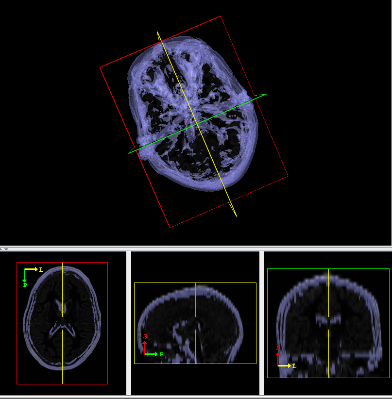
Figure 10 shows the surface extracted using the Intensity Level option. | |||
<div> </div><div> | |||
{| border="1" cellpadding="5" | {| border="1" cellpadding="5" | ||
|+ <div>'''Figure | |+ <div>'''Figure 10. The view of the surface extracted using the Intensity Level option''' </div> | ||
|- | |- | ||
| | | | ||
<div style="font-style: normal; font-weight: normal; margin-bottom: 0pt; margin-left: 0pt; margin-right: 0pt; margin-top: 1pt; text-align: left; text-decoration: none; text-indent: 0pt; text-transform: none; vertical-align: baseline"><font size="2pt"><font color="#000000"><div><center>[[Image: | <div style="font-style: normal; font-weight: normal; margin-bottom: 0pt; margin-left: 0pt; margin-right: 0pt; margin-top: 1pt; text-align: left; text-decoration: none; text-indent: 0pt; text-transform: none; vertical-align: baseline"><font size="2pt"><font color="#000000"><div><center>[[Image:SurfaceFromIntensityLevelEq26.png]]</center></div><br /> </font></font></div> | ||
|} | |} | ||
</div> | </div> | ||
[<sup>1</sup>]Please, note that the Resampling in a lengthy process. Give some consideration to values you choose for Z. The algorithm's speed also depends on the MIPAV memory allocation settings. Resample size also depends on the amount of memory on the graphics card. <br /> | |||
== See also: == | |||
*[http://mipav.cit.nih.gov/wiki/index.php/Main_Page MIPAV WIKI page] | |||
*[[Understanding MIPAV capabilities]] | |||
**[[Understanding MIPAV capabilities]] | |||
**[[Developing new tools using the API]] | |||
*[[Using MIPAV Algorithms]] | |||
**[[Extract Brain: Extract Brain Surface (BET)]] | |||
**[[Extract Brain: Extract Brain Surface (BSE)]] | |||
**[[Face Anonymizer (BET)]] | |||
[[Category:Help]] | [[Category:Help]] | ||
[[Category:Help:Algorithms]] | [[Category:Help:Algorithms]] | ||
Revision as of 19:10, 11 May 2012
The Extract Surface algorithm described in this section is based on the Marching Cubes algorithm, which was designed by William E. Lorensen and Harvey E. Cline to extract surface information from a 3D array of values. The applications of this algorithm are mainly concerned with medical visualizations such as CT and MRI scan data images.
Background
The basic notion of the algorithm is that we can define a voxel by the pixel values at the eight corners of the cube. We also can define an isosurface which intersects the cube, refer to Figures 1 and 2. If one or more pixels of a voxel have values less than the user-specified isovalue, and one or more have values greater than this value, we know that the voxel must contribute some component of the isosurface.
By determining which edges of the voxel are intersected by the isosurface, we can create triangular patches that divide the voxel between regions within the isosurface and regions outside. By connecting the patches from all voxel on the isosurface boundary, we get a surface representation.
The indexing convention for vertices and edges used in the algorithm is shown in Figure 1 below.
|
Example: If for example, the value at vertex 3 is below the isosurface value and all the values of all the other vertices are above the isosurface value, then we would create a triangular facet which cuts through edges 2,3, and 11 as shown in Figure 2. The exact position of the vertices of the triangular facet depends on the relationship of the isosurface value to the values at the vertices 3-2, 3-0, 3-7 respectively. |
Therefore, we must specify a threshold value, first. For this value, some voxels will be entirely inside or outside the corresponding isosurface and some voxels will be intersected by the isosurface. In the first pass of the algorithm, the voxels that are intersected by the threshold value are identified. In the second pass, these voxels are examined and a set of one or more polygons is produced. These polygons are then output for rendering.
Each of the voxel's 8 vertices can be either inside or outside of the isosurface value, thus, there are 2'8' = 256 possible ways how an isosurface can intersect the voxel. To simplify the algorithm, we can reduce this complexity by assuming that cell combinations are duplicated under the following conditions:
- Rotating by any degree over any of the 3 primary axis (X,Y, or Z);
- Mirroring the isosurface's shape across any of the 3 primary axis;
- Inverting all corners and flipping the normals of the relating polygons.
By taking this symmetry into account, we can reduce the original 256 combinations to a total of 15 combinations, refer to Figure 3.
Now we can use a table (called edgeTable) which maps the vertices under the isosurface to the intersecting edges. An 8 bit index can be formed from the table where each bit corresponds to a vertex, refer to [MarchingCubes.html#wp1780799 Table 1].
Looking up the edgeTable returns a 12 bit number, each bit corresponding to an edge. 0 if the edge isn't cut by the isosurface and 1 if the edge is cut by the isosurface. If none of the edges are cut the table returns zero. This occurs when the cubeindex is 0, which means that all vertices are below the isosurface, or 0xff (all vertices above the isosurface).
Using the example shown in Figure 1, where only vertex 3 was below the isosurface, cubeindex would equal 0000 1000 or 8. The edgeTable{8} equals 1000 0000 1100. This means that edge 2,3, and 11 are intersected by the isosurface, refer to Figure 2.
Now the intersection points can be calculated by linear interpolation. If P1 and P2 are the vertices of a cut edge and V1 and V2 are the scalar values of each vertex, the intersection point P is given by the following equation:
The last part of the algorithm involves forming the correct triangular facets from the positions where the isosurface intersects the edges of the grid cell. In order to do that, another table (also called triTable) is used. This table uses the same cubeindex from edgeTable, but allows the vertex sequence to be searched for as many triangular facets as necessary to represent the isosurface within the grid cell. Each of the non-trivial configurations results in between 1 and 4 triangles is added to the isosurface. The actual vertices themselves can be computed either by interpolating along the edges, or, by default their location to the middle of the edge.
Since we can create surface patches for a single voxel, we can apply this algorithm to the entire volume.We can either treat each cube independently, or we can propagate edge intersections between the cubes which share the edges. The sharing of edge/vertex information also results in a more compact model.
References
The following sources were used:
Lorensen, W.E. and Cline, H.E., Marching Cubes: a high resolution 3D surface reconstruction algorithm, Computer Graphics, Vol. 21, No. 4, pp 163-169 (Proc. of SIGGRAPH), 1987.
Paul Bourke, Polygonising a scalar field Also known as: "3D Contouring," "Marching Cubes," "Surface Reconstruction;" May 1994, http://local.wasp.uwa.edu.au/~pbourke/modelling/polygonise/
Image types
You can apply the Extract Surface algorithm to any type of images using in MIPAV.
Output Files
The output of the algorithm is a set of vertices and normals as well as the map that shows how the vertices are connected. This information can be saved in following formats:
- Tab-delimited (*.txt);
- Surface (*.sur), which is MIPAV format. A surface file contains the above information plus the additional information that describes the surface color and more. This is defined by an XML scheme, which can be found on the MIPAV web site (http://mipav.cit.nih.gov/documentation/xml-format/image/);
- VRML (*.wrl), which can then be processed by any application that can read and display VRML objects.
Applying the Extract Surface Algorithm
To run the algorithm, complete the following steps:
- Open an image of interest;
- Select Algorithms > Extract Surface (marching cubes);
- The Extract Surface dialog box opens. Here, you can choose to apply following three options:
- You may select a VOI region, and then apply the algorithm to the selected VOI;
- You may apply a mask to the image first, and then run the algorithm;
- Or you may extract a surface from the region with a chosen intensity level.
- Select a type and location of the output file. You can save the result as a *.txt file (in Tab-delimited format), *.wrl file, or surface file (*.sur). Refer to Section [MarchingCubes.html#wp1785344 "Output Files"]for more information.
- Press OK.
The algorithm begins to run, and a progress bar appears with the status. When the algorithm finishes running, the progress bar disappears, and the results appear as a file in selected format in a chosen location. For more information about the dialog box options, refer to Figure 4.
|
VOI Region
|
Applies the algorithm to the volume delineated by the VOI.
|
|
|
Mask Image
|
Applies the algorithm to the volume within a chosen mask. You must apply the mask, first.
| |
|
Intensity Level
|
Applies the algorithm to the region with the chosen intensity level. By default, the intensity level value is set to 50.
| |
|
Blur by (Std.Dev.)
|
Blurs the image to improve the extracted surface. The value specifies the standard deviation of the Gaussian filter used to regularize the image.
| |
|
Decimate Surface
|
If selected, reduces the count of triangle facets, which results the more compact algorithm.
| |
|
Choose
|
Use this button to select a catalogue where you would like to store your results and choose a file format (*.txt, *.sur, or *.wrl).
| |
|
OK
|
Applies the algorithm according to the specifications in this dialog box.
| |
|
Cancel
|
Disregards any changes that you made in this dialog box and closes it.
| |
|
Help
|
Displays online help for this dialog box.
| |
Examples
1. To apply the algorithm to a VOI region:
- Open an image of interest.
- Delineate a VOI on the image, and then call the Algorithms> Extract Surface (marching cubes).
- In the Extract Surface dialog box that appears, select the VOI Region option.
- Select the surface file type as an output, and then specify the file name and location.
- Press OK. The algorithm begins to run, and a progress bar appears showing the status.
- When the algorithm finishes running and the progress bar disappears, click the Volume Tri-planar View icon on the MIPAV toolbar.
- The Resample dialog box appears. See Figure 5.
- In the Expected Extents box, specify the value for the Z direction. The value must be in a power of two (32, 64, 128, 256). Refer to Figure 5. The bigger number you choose, the higher resolution you receive.[1]
- Press Resample to proceed.
- The 3D viewer opens for the selected image.
- Click the Add Surface to Viewer icon and add the surface file from Step 5 to the Surface list. Then, select the file name and press Add.
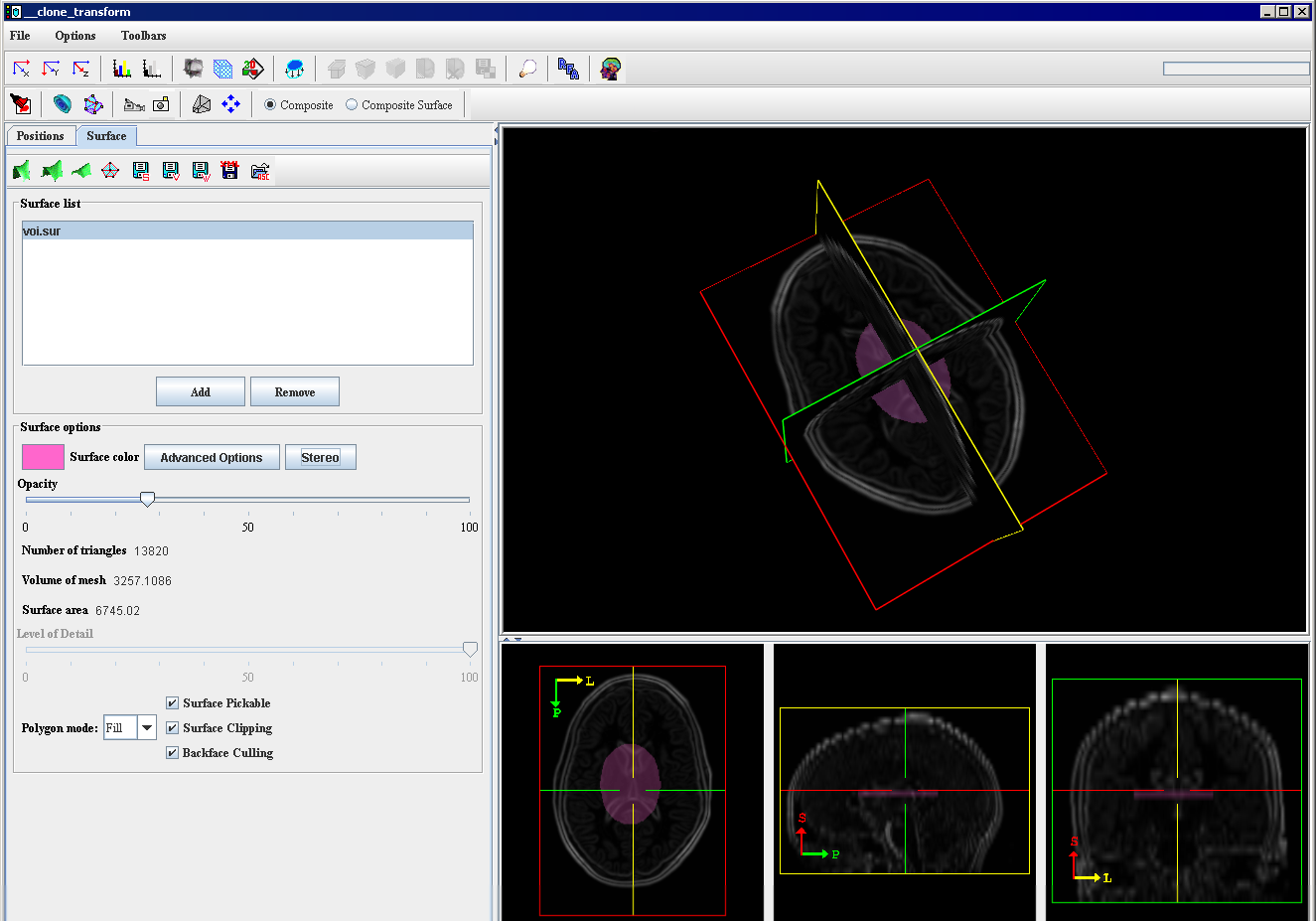
- The surface will be added to the image. To adjust the display of the image, use the Surface options, such as color and opacity. Refer to Figure 6.
2. To use the Mask Image option:
- Open an image of interest.
- Create a mask.
- Call the Algorithms> Extract Surface (marching cubes).
- In the dialog box that appears, select the Mask Image option.
- Select the surface file as an output, and then specify the file name and location. Press OK.
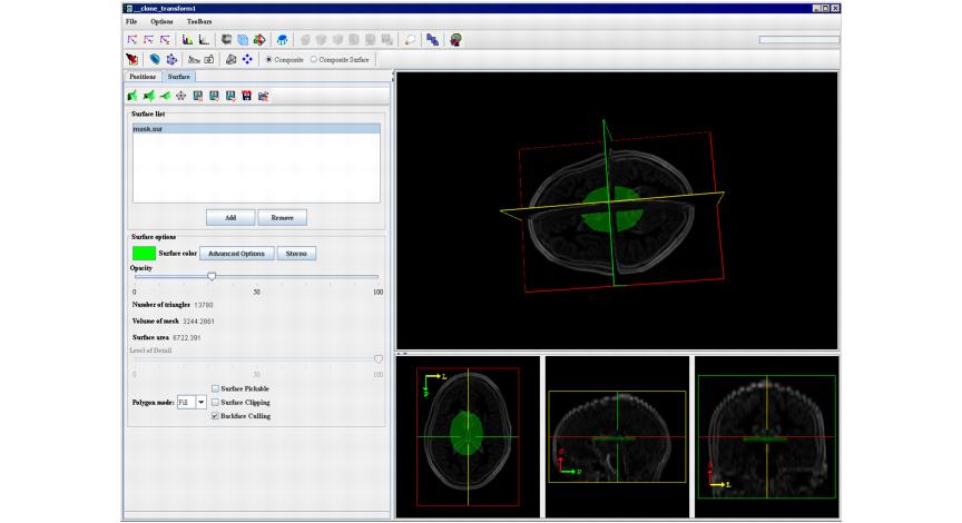
- When the algorithm finishes running, click the Volume Tri-planar View icon on the MIPAV toolbar and follow the steps 6--12 from the first example. Refer to Figure 7.
3. To use the Intensity Level option:
- Open an image of interest.
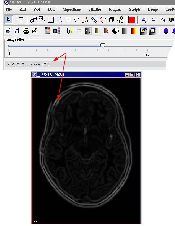
- Select the intensity level value. You can understand the intensity level by mousing over the image. The intensity value for the selected pixel is shown on the main MIPAV toolbar.
- Call the Algorithms> Extract Surface (marching cubes).
- In the dialog box that appears, select the Intensity Level option.
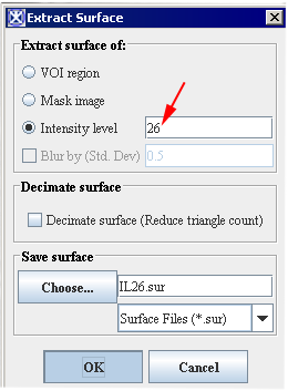
- Enter the intensity value that you would like to apply. Refer to Figures 8 and 9.
- Select the surface file as an output, and specify the file name and location. Press OK to run the algorithm.
- When the algorithm finishes running, click the Volume Tri-planar View icon on the MIPAV toolbar and follow the steps 7-12 from the first example on Marching Cubes.
Figure 10 shows the surface extracted using the Intensity Level option.
[1]Please, note that the Resampling in a lengthy process. Give some consideration to values you choose for Z. The algorithm's speed also depends on the MIPAV memory allocation settings. Resample size also depends on the amount of memory on the graphics card.
