Extract Brain: Extract Brain Surface (BET) and Extract Brain: Extract Brain Surface (BSE): Difference between pages
m (1 revision imported) |
MIPAV>Olga Vovk m (→References) |
||
| Line 1: | Line 1: | ||
This algorithm | This algorithm strips areas outside the brain from a T1-weighted magnetic resonance image (MRI). It is based on the Brain Surface Extraction (BSE) algorithms developed at the Signal and Image Processing Institute at the University of Southern California by David W. Shattuck. This is MIPAV's interpretation of the BSE process and may produce slightly different results compared to other BSE implementations. | ||
=== Background === | === Background === | ||
This algorithm works to isolate the brain from the rest of a T1-weighted MRI using a series of image manipulations. Essentially, it relies on the fact that the brain is the largest area surrounded by a strong edge within an MRI of a patient's head. There are essentially four phases to the BSE algorithm: | |||
* Step 1, | * Step 1, Filtering the image to remove irregularities. | ||
* Step 2, | * Step 2, Detecting edges in the image. | ||
* Step 3, | * Step 3, Performing morphological erosions and brain isolation. | ||
* Step 4, | * Step 4, Performing surface cleanup and image masking. | ||
==== Step 1, | ==== Step 1, Filtering the image to remove irregularities ==== | ||
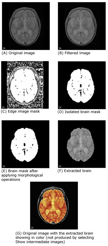
The first step that MIPAV performs is to filter the original image to remove irregularities, thus making the next step-edge detection-easier. The filter chosen for this was the Filters (Spatial): Regularized Isotropic (Nonlinear) Diffusion. Figure 1-A shows the original image, and Figure 1-B shows the image after it is filtered. | |||
==== Step 2, Detecting edges in the image ==== | |||
Next, MIPAV performs a thresholded zero-crossing detection of the filtered image's laplacian. This process marks positive areas of the laplacian image as objects by setting them to 1 and identifies nonobject areas by setting their values to 0 (Figure 1-C). | |||
==== Step | ==== Step 3, Performing morphological erosions and brain isolation ==== | ||
During this step, the software performs a number of 3D (or, optionally, 2.5D) morphological erosions on the edge image mask to remove small areas identified as objects that are not a part of the brain. It then performs a search for the largest 3D region within the image, which should be the brain (Figure 1-D). It erases everything outside this region and then performs another morphological operation, dilating the brain image back to approximately its original size and shape before the erosion (Figure 1-E). | |||
==== Step 4, Performing surface cleanup and image masking ==== | |||
Once MIPAV isolates the brain, it needs to clean up the segmentation a bit by performing more morphological operations. It first performs a 2.5D closing with a circular kernel in an attempt to fill in interior gaps and holes that may be present. Since it is better to have too much of the original volume in the extracted brain than to miss some of the brain, MIPAV performs an extra dilation during the closing operation, making the mask image slightly larger. If a smaller mask is desired, the closing kernel size can be reduced (keep in mind that this size is in millimeters and is the diameter of the kernel, not its radius). | |||
As an option, MIPAV can then fill in any holes that still exist within the brain mask. Finally, it uses the mask to extract the brain image data from the original volume (Figure1-F). | |||
==== Selecting parameters ==== | |||
Careful parameter selection must be done for the BSE algorithm to produce good results. For example, excessive erosion or dilation, closing kernel size, or edge detection kernel size can remove detail from the brain surface or remove it completely. | |||
===== Edge detection kernel size parameter ===== | |||
The edge detection kernel size parameter is especially sensitive. Small changes to it (e.g., from the default of 0.6 up to 0.7 or down to 0.5 in the following example) can result in large changes to the extracted brain volume. Refer to Figure 1. | |||
{| width="90%" border="1" frame="hsides" frame="hsides" | |||
{| border="1" | |||
|- | |- | ||
| | | width="9%" valign="top" | | ||
[[Image:recommendationicon.gif]] | |||
| width="81%" bgcolor="#B0E0E6" | '''Recommendation:''' To find an optimal set of parameters values, run this algorithm repeatedly on a representative volume of the MRI images that you want to process with different parameter values and with Show intermediate images selected. | |||
|} | |} | ||
<br /> | |||
Figure 1 shows images that were produced from running this algorithm with the default parameters against a 256 x 256 x 47 MRI. In each image, the middle slice is shown. | |||
==== Image types ==== | |||
The | You can apply this algorithm only to 3D MRI images. The resulting image is of the same data type as the original image. | ||
==== References ==== | |||
Refer to the following references for more information about the Brain Surface Extraction algorithm and general background information on brain extraction algorithms. | |||
A. I. Scher, E. S. C. Korf, S. W. Hartley, L. J. Launer. "An Epidemiologic Approach to Automatic Post-Processing of Brain MRI." | |||
David W. Shattuck, Stephanie R. Sandor-Leahy, Kirt A. Schaper, David A. Rottenburg, Richard M. Leahy. "Magnetic Resonance Image Tissue Classification Using a Partial Volume Model." ''NeuroImage'' 2001; 13(5):856-876. | |||
< | <div> </div><div> | ||
</ | |||
<div> | |||
{| border="1" cellpadding="5" | {| border="1" cellpadding="5" | ||
|+ <div>'''Figure | |+ <div>'''Figure 1. Examples of Extract Brain Surface (BSE) image processing''' </div> | ||
|- | |- | ||
| | | rowspan="1" colspan="2" | | ||
<div><div | <div><div><center>[[Image:exampleBSE_BeforeAfter.jpg]]</center></div> </div> | ||
|} | |} | ||
</div> | </div> | ||
= | <div id="ApplyingBSE"><div> | ||
=== Applying BSE === | |||
=== Applying | |||
To use this algorithm, do the following: | To use this algorithm, do the following: | ||
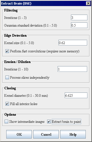
# Select Algorithms > Extract Brain. The | # Select Algorithms > Extract Brain Surface (BSE). The Extract Brain Surface (BSE) dialog box opens (Figure 2). | ||
# Complete the information in the dialog box. | # Complete the information in the dialog box. | ||
# Click OK. The algorithm begins to run, and a progress bar appears with the status. When the algorithm finishes running, the progress bar disappears, and the results replace the original image. | # Click OK. The algorithm begins to run, and a progress bar appears with the status. When the algorithm finishes running, the progress bar disappears, and the results replace the original image. | ||
<div> | <div> | ||
{| border="1" cellpadding="5" | {| border="1" cellpadding="5" | ||
|+ <div>'''Extract Brain dialog box ''' | |+ <div>'''Figure 2. Extract Brain Surface (BSE) algorithm dialog box ''' </div> | ||
|- | |- | ||
| | | | ||
<div> | <div>Filtering </div> | ||
| | | | ||
<div> | | rowspan="3" colspan="1" | | ||
<div><div><center>[[Image:ExtractBrainBSEDialogbox.jpg]]</center></div> </div> | |||
|- | |- | ||
| | | | ||
<div>''' | <div>'''Iterations (1-5)''' </div> | ||
| | | | ||
<div> | <div>Specifies the number of regularized isotropic (nonlinear) diffusion filter passes to apply to the image. This parameter is used to find anatomical boundaries seperating the brain from the skull and tissues. For images with a lot of noise, increasing this parameter will smoth noisy regions while maintaining image boundaries. </div> | ||
|- | |- | ||
| | | | ||
<div>''' | <div>'''Gaussian standard deviation (0.1-5.0)''' </div> | ||
| | | | ||
<div> | <div>Specifies the standard deviation of the Gaussian filter used to regularize the image. A higher standard deviation gives preference to high-contrast edges for each voxel in the region. </div> | ||
|- | |||
| rowspan="1" colspan="3" | | |||
<div>Edge Detection </div> | |||
|- | |- | ||
| | | | ||
<div>''' | <div>'''Kernel size (0.1-5.0)''' </div> | ||
| rowspan="1" colspan="2" | | |||
<div>Specifies the size of the symmetric Gaussian kernel to use in the Laplacian Edge Detection algorithm. An increase in kernel size will yield an image which contains only the strongest edges. Equivalent to using a narrow filter on the image, a small kernal size will result in more edges. </div> | |||
|- | |||
| | | | ||
<div> | <div>'''Perform fast convolutions (requires more memory)''' </div> | ||
| rowspan="1" colspan="2" | | |||
<div>Specifies whether to perform Marr-Hildreth edge detection with separable image convolutions. </div><div>The separable image convolution completes about twice as fast, but it requires approximately three times more memory. If memory is not a constraint, select this check box. </div> | |||
|- | |- | ||
| | | rowspan="1" colspan="3" | | ||
<div> | <div>Erosion/Dilation </div> | ||
|- | |- | ||
| | | | ||
<div>''' | <div>'''Iterations (1-10)''' </div> | ||
| | | rowspan="1" colspan="2" | | ||
<div>Specifies the | <div>Specifies the number of: </div> | ||
* Erosions that should be applied to the edge image before the brain is isolated from the rest of the volume; | |||
* Dilations to perform afterward. | |||
<div>A higher number of iterations will help distinguish brain tissue from blood vessels and the inner cortical surface. Noise resulting from blood vessels or low image contrast may be present when few iterations are used. </div> | |||
|- | |- | ||
| | | | ||
<div>''' | <div>'''Process slices independently''' </div> | ||
| | | rowspan="1" colspan="2" | | ||
<div> | <div>Applies the algorithm to each slice of the dataset independently. Separable image operations will again produce results more quickly while using increased memory. Since this part of the brain surface extraction is meant to fill large pits and close holes in the surface, indepent processing may not yield optimal results. </div> | ||
|- | |- | ||
| | | rowspan="1" colspan="3" | | ||
<div>Closing </div> | |||
| | |||
<div> | |||
|- | |- | ||
| | | | ||
<div>''' | <div>'''Kernel diameter (in mm) (0.1-50.0)''' </div> | ||
| | | rowspan="1" colspan="2" | | ||
<div> | <div>Specifies the size of the kernel to use (in millimeters). The value defaults to a number of millimeters that ensures that the kernel is 6 pixels in diameter and takes into account the volume resolutions. Closing operations act to fill smaller pits and close holes in the segmented brain tissue. </div> | ||
|- | |- | ||
| | | | ||
<div>''' | <div>'''Fill all interior holes''' </div> | ||
| | | rowspan="1" colspan="2" | | ||
<div> | <div>Fills in any holes that still exist within the brain mask. When optimal parameters for a given image have been used, this option will generally produce a volume of interest that lies between the inner cortical surface and the outer cortical boundary. </div> | ||
|- | |- | ||
| | | rowspan="1" colspan="3" | | ||
<div>Options </div> | |||
| | |||
<div> | |||
|- | |- | ||
| | | | ||
<div>''' | <div>'''Show intermediate images''' </div> | ||
| | | rowspan="1" colspan="2" | | ||
<div> | <div>Shows, when selected, in addition to the final brain image, the images that are generated at various points while the BSE algorithm is running. Selecting this check box may help you in finding the optimal parameters for running the BSE algorithm on a volume. </div><div>For an image named ''ImageName'', the debugging images displayed would include: </div> | ||
* The filtered image (named ''ImageName_filter'') | |||
* The edge image (named ''ImageName_edge'') | |||
* The eroded edge image (named ''ImageName_erode_brain'') | |||
* The isolated brain mask after erosion and dilation (named ''ImageName_erode_brain_dilate'') | |||
* The brain mask after closing (named ''ImageName_close'') | |||
* The closing image is shown before any interior mask holes are filled | |||
|- | |- | ||
| | | | ||
<div> | <div>Extract brain to paint </div> | ||
| | | rowspan="1" colspan="2" | | ||
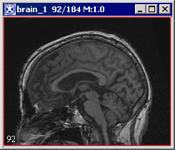
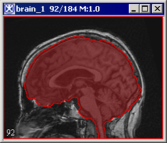
<div> | <div>Paints the extracted brain onto the current image. See also Figure 3. </div> | ||
|- | |- | ||
| | | | ||
<div>'''OK''' </div> | <div>'''OK''' </div> | ||
| | | rowspan="1" colspan="2" | | ||
<div>Applies the algorithm according to the specifications in this dialog box. </div> | <div>Applies the algorithm according to the specifications in this dialog box. </div> | ||
|- | |- | ||
| | | | ||
<div>'''Cancel''' </div> | <div>'''Cancel''' </div> | ||
| | | rowspan="1" colspan="2" | | ||
<div>Disregards any changes that you made in the dialog box and closes this dialog box. </div> | <div>Disregards any changes that you made in the dialog box and closes this dialog box. </div> | ||
|- | |- | ||
| | | | ||
<div>'''Help''' </div> | <div>'''Help''' </div> | ||
| rowspan="1" colspan="2" | | |||
<div>Displays online help for this dialog box. </div> | |||
|} | |||
</div><div> | |||
{| border="1" cellpadding="5" | |||
|+ <div>'''Figure 3. The Extract Brain to Paint option: on your left is the original image and on your right is the result image with the brain extracted to paint.''' </div> | |||
|- | |||
| | | | ||
<div> | <div style="font-style: normal; font-weight: normal; margin-bottom: 0pt; margin-left: 0pt; margin-right: 0pt; margin-top: 1pt; text-align: left; text-decoration: none; text-indent: 0pt; text-transform: none; vertical-align: baseline"><font size="2pt"><font color="#000000"><div><center>[[Image:ExtractBrainIntoPaint1.jpg]]</center></div><br /> </font></font></div> | ||
| | |||
<div style="font-style: normal; font-weight: normal; margin-bottom: 0pt; margin-left: 0pt; margin-right: 0pt; margin-top: 1pt; text-align: left; text-decoration: none; text-indent: 0pt; text-transform: none; vertical-align: baseline"><font size="2pt"><font color="#000000"><div><center>[[Image:ExtractBrainIntoPaint2.jpg]]</center></div><br /> </font></font></div> | |||
|} | |} | ||
</div> | |||
[[Category:Help]] | [[Category:Help]] | ||
[[Category:Help:Algorithms]] | [[Category:Help:Algorithms]] | ||
Revision as of 20:48, 20 July 2012
This algorithm strips areas outside the brain from a T1-weighted magnetic resonance image (MRI). It is based on the Brain Surface Extraction (BSE) algorithms developed at the Signal and Image Processing Institute at the University of Southern California by David W. Shattuck. This is MIPAV's interpretation of the BSE process and may produce slightly different results compared to other BSE implementations.
Background
This algorithm works to isolate the brain from the rest of a T1-weighted MRI using a series of image manipulations. Essentially, it relies on the fact that the brain is the largest area surrounded by a strong edge within an MRI of a patient's head. There are essentially four phases to the BSE algorithm:
- Step 1, Filtering the image to remove irregularities.
- Step 2, Detecting edges in the image.
- Step 3, Performing morphological erosions and brain isolation.
- Step 4, Performing surface cleanup and image masking.
Step 1, Filtering the image to remove irregularities
The first step that MIPAV performs is to filter the original image to remove irregularities, thus making the next step-edge detection-easier. The filter chosen for this was the Filters (Spatial): Regularized Isotropic (Nonlinear) Diffusion. Figure 1-A shows the original image, and Figure 1-B shows the image after it is filtered.
Step 2, Detecting edges in the image
Next, MIPAV performs a thresholded zero-crossing detection of the filtered image's laplacian. This process marks positive areas of the laplacian image as objects by setting them to 1 and identifies nonobject areas by setting their values to 0 (Figure 1-C).
Step 3, Performing morphological erosions and brain isolation
During this step, the software performs a number of 3D (or, optionally, 2.5D) morphological erosions on the edge image mask to remove small areas identified as objects that are not a part of the brain. It then performs a search for the largest 3D region within the image, which should be the brain (Figure 1-D). It erases everything outside this region and then performs another morphological operation, dilating the brain image back to approximately its original size and shape before the erosion (Figure 1-E).
Step 4, Performing surface cleanup and image masking
Once MIPAV isolates the brain, it needs to clean up the segmentation a bit by performing more morphological operations. It first performs a 2.5D closing with a circular kernel in an attempt to fill in interior gaps and holes that may be present. Since it is better to have too much of the original volume in the extracted brain than to miss some of the brain, MIPAV performs an extra dilation during the closing operation, making the mask image slightly larger. If a smaller mask is desired, the closing kernel size can be reduced (keep in mind that this size is in millimeters and is the diameter of the kernel, not its radius).
As an option, MIPAV can then fill in any holes that still exist within the brain mask. Finally, it uses the mask to extract the brain image data from the original volume (Figure1-F).
Selecting parameters
Careful parameter selection must be done for the BSE algorithm to produce good results. For example, excessive erosion or dilation, closing kernel size, or edge detection kernel size can remove detail from the brain surface or remove it completely.
Edge detection kernel size parameter
The edge detection kernel size parameter is especially sensitive. Small changes to it (e.g., from the default of 0.6 up to 0.7 or down to 0.5 in the following example) can result in large changes to the extracted brain volume. Refer to Figure 1.
| Recommendation: To find an optimal set of parameters values, run this algorithm repeatedly on a representative volume of the MRI images that you want to process with different parameter values and with Show intermediate images selected. |
Figure 1 shows images that were produced from running this algorithm with the default parameters against a 256 x 256 x 47 MRI. In each image, the middle slice is shown.
Image types
You can apply this algorithm only to 3D MRI images. The resulting image is of the same data type as the original image.
References
Refer to the following references for more information about the Brain Surface Extraction algorithm and general background information on brain extraction algorithms.
A. I. Scher, E. S. C. Korf, S. W. Hartley, L. J. Launer. "An Epidemiologic Approach to Automatic Post-Processing of Brain MRI."
David W. Shattuck, Stephanie R. Sandor-Leahy, Kirt A. Schaper, David A. Rottenburg, Richard M. Leahy. "Magnetic Resonance Image Tissue Classification Using a Partial Volume Model." NeuroImage 2001; 13(5):856-876.
Applying BSE
To use this algorithm, do the following:
- Select Algorithms > Extract Brain Surface (BSE). The Extract Brain Surface (BSE) dialog box opens (Figure 2).
- Complete the information in the dialog box.
- Click OK. The algorithm begins to run, and a progress bar appears with the status. When the algorithm finishes running, the progress bar disappears, and the results replace the original image.
|
Filtering
|
||
|
Iterations (1-5)
|
Specifies the number of regularized isotropic (nonlinear) diffusion filter passes to apply to the image. This parameter is used to find anatomical boundaries seperating the brain from the skull and tissues. For images with a lot of noise, increasing this parameter will smoth noisy regions while maintaining image boundaries.
| |
|
Gaussian standard deviation (0.1-5.0)
|
Specifies the standard deviation of the Gaussian filter used to regularize the image. A higher standard deviation gives preference to high-contrast edges for each voxel in the region.
| |
|
Edge Detection
| ||
|
Kernel size (0.1-5.0)
|
Specifies the size of the symmetric Gaussian kernel to use in the Laplacian Edge Detection algorithm. An increase in kernel size will yield an image which contains only the strongest edges. Equivalent to using a narrow filter on the image, a small kernal size will result in more edges.
| |
|
Perform fast convolutions (requires more memory)
|
Specifies whether to perform Marr-Hildreth edge detection with separable image convolutions. The separable image convolution completes about twice as fast, but it requires approximately three times more memory. If memory is not a constraint, select this check box.
| |
|
Erosion/Dilation
| ||
|
Iterations (1-10)
|
Specifies the number of:
A higher number of iterations will help distinguish brain tissue from blood vessels and the inner cortical surface. Noise resulting from blood vessels or low image contrast may be present when few iterations are used.
| |
|
Process slices independently
|
Applies the algorithm to each slice of the dataset independently. Separable image operations will again produce results more quickly while using increased memory. Since this part of the brain surface extraction is meant to fill large pits and close holes in the surface, indepent processing may not yield optimal results.
| |
|
Closing
| ||
|
Kernel diameter (in mm) (0.1-50.0)
|
Specifies the size of the kernel to use (in millimeters). The value defaults to a number of millimeters that ensures that the kernel is 6 pixels in diameter and takes into account the volume resolutions. Closing operations act to fill smaller pits and close holes in the segmented brain tissue.
| |
|
Fill all interior holes
|
Fills in any holes that still exist within the brain mask. When optimal parameters for a given image have been used, this option will generally produce a volume of interest that lies between the inner cortical surface and the outer cortical boundary.
| |
|
Options
| ||
|
Show intermediate images
|
Shows, when selected, in addition to the final brain image, the images that are generated at various points while the BSE algorithm is running. Selecting this check box may help you in finding the optimal parameters for running the BSE algorithm on a volume. For an image named ImageName, the debugging images displayed would include:
| |
|
Extract brain to paint
|
Paints the extracted brain onto the current image. See also Figure 3.
| |
|
OK
|
Applies the algorithm according to the specifications in this dialog box.
| |
|
Cancel
|
Disregards any changes that you made in the dialog box and closes this dialog box.
| |
|
Help
|
Displays online help for this dialog box.
| |


