Extract Brain: Extract Brain Surface (BET)
This algorithm extracts the surface of the brain from a T1-weighted MRI, eliminating the areas outside of the brain. This algorithm is similar to the brain extraction tool developed at the Oxford Center for Functional Magnetic Resonance Imaging of the Brain.
Contents
Background
The procedure used by this algorithm to extract the brain surface consists of four major steps:
- Step 1, Estimating image parameters
- Step 2, Selecting an initial closed mesh within the brain
- Step 3, Evolving a mesh in a surface tangent direction, in a surface normal direction, and in a vertex normal direction
- Step 4, Identifying the voxels inside and on the brain surface
Step 1, Estimating image parameters
A number of important parameters must be calculated from histograms composed of 1024 bins. These parameters are used to estimate the initial axes of the ellipsoid. As well as affect the evolution of an initial ellipsoid to the surface of the brain. Using an ellipsoid to initial surface as opposed to a sphere significantly improves the segmentation especially around the eyes and sinus cavities.
There are three such intensity values:
- Minimum threshold: tmin = 0.5 background threshold
- Background threshold: tback = histogram index with the greatest count
- Median threshold: tmed = median pixel value with the initial ellipsoid that are greater than tback
Step 2, Selecting an initial closed mesh
MIPAV uses a different approach to constructing an initial mesh (i.e., ellipsoid), which is used as the initial surface for approximating the brain surface. The final approximation to the brain surface lies near the CSF and scalp. The shape of the mesh at the top of the head is nearly the shape of the scalp.
As a way of identifying the scalp voxels that lie at the top of the head, this algorithm locates all the bright voxels using the threshold tbright. Voxels in the lower half of the head also show up due to fatty tissue, much of it at the base of the neck. Empirically, the number of bright voxels near the scalp at the top of the head appear to be noticeably smaller than those voxels in the bottom half of the head. This algorithm stores only those voxels that are near the scalp at the top of the head. The voxel locations are fit with an ellipsoid by means of a least squares algorithm for estimating the coefficients of the quadratic equation that represent the ellipsoid.
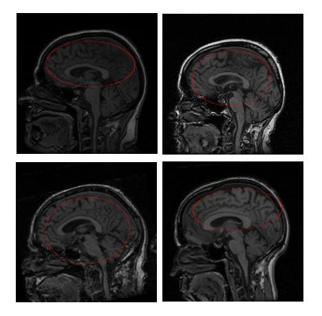
The ellipsoid obtained is reduced in scale by approximately half. The initial ellipsoids in all the test images evolved to reasonable brain surface approximations in a reasonable amount of time. Figure 1 shows the ellipsoid of intersection of the ellipsoid with the middle slice of the images.
| Note: If it is unable to calculate the parameters to form an ellipsoid, MIPAV estimates a sphere instead to initialize the surface extraction process. |
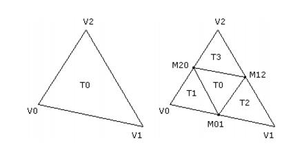
The ellipsoid is topologically equivalent to a sphere centered at the origin and with unit radius. Therefore, the initial mesh that approximates an ellipsoid is constructed by tessellating this sphere and then by applying an affine transformation to map the sphere-mesh vertices to ellipsoid-mesh vertices. The tessellation is performed by starting with an octahedron inscribed in the sphere. The octahedron vertices are (�1, 0, 0), (0,�1, 0), and (0, 0,�1). There are initially 6 vertices, 12 edges, and 8 triangles. Each level of subdivision requires computing the midpoints of the edges and replacing each triangle by four subtriangles as shown in Figure 2.
To avoid a lot of dynamic allocation of memory, it is possible to compute the total number of vertices, edges, and triangles that are required for the mesh given the number of subdivisions. Let V0, E0, and T0 be the current quantities of vertices, edges, and triangles. Each subdivide edge leads to a new vertex, so the new number of vertices is V1 = V0 E0. Each triangle is replaced by four triangles, so the new number of triangles is T1 = 4T0. Each edge is split into two edges and each subdivided triangle creates three additional edges, so the new number of edges is
E1 = 2E0 3T0. These recurrence formulas are iterated over the desired number of subdivisions to compute the total objects required.
All edges are subdivided first. When each edge is subdivided, the index of the newly generated vertex must be stored for later use by triangle sharing the edge that is being subdivided. A hash map is used to store an edge as a pair of vertex indices as the key of the map. The value of the map is the index of the vertex that is generated as the midpoint. The triangles are then subdivided. The edges of the triangle are looked up in the hash map to find the indices of the three new vertices to be used by the subtriangles.
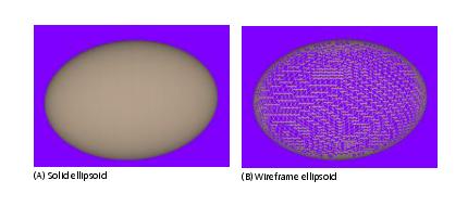
The subtriangles are stored as triples of vertex indices. After the triangles are subdivided, the original edges must all be discarded and replaced by the subdivided edges in the new mesh. These steps are repeated for all subdivision steps. Once the subdivided mesh is generated, we also need to know the vertices adjacent to a given vertex. This information is required to compute the average of the neighboring vertices. The mean length of all the edges of the mesh can be computed using the edge hash map as storage for the edges, so after triangle division the edge hash map must exist throughout the mesh updates. Figure 3 shows a rendering of an initial ellipsoid, both solid and wireframe.
The median intensity threshold, tmed, is obtained by iterating over all the voxels with the image with intensity larger than tback and which are located inside the initial ellipsoid. The corresponding set of intensities is sorted and the middle value selected for the median intensity threshold.
Step 3, Evolution of the mesh
The first step is to compute the average edge length L of the edges in the mesh. This is easily done by iterating over the hash map of edges, looking up the vertices from the indices stored in each edge, calculating the edge length, accumulating the lengths, then dividing by the total number of edges.
Second, the vertex normals are needed for evolving the mesh in a direction normal to the surface. This is also easily done by iterating over the triangles. A running sum of non-unit triangle normals is maintained for each vertex. Once the sums are calculated, the vertex normals are normalized by an iteration over the array storing them.
Third, the surface tangents, normals, and curvatures must be computed. If ![]() is a vertex, then
is a vertex, then ![]() is the average of all the neighbors of
is the average of all the neighbors of ![]() . The neighbors are rapidly accessed by using the adjacency structure that keeps track of the array of indices of neighbors for each vertex, so the mean vertex is easily computed. The difference between vertex and mean is
. The neighbors are rapidly accessed by using the adjacency structure that keeps track of the array of indices of neighbors for each vertex, so the mean vertex is easily computed. The difference between vertex and mean is ![]() . This vector is decomposed into a surface normal and surface tangential component. The normal component is in the direction of the vertex normal
. This vector is decomposed into a surface normal and surface tangential component. The normal component is in the direction of the vertex normal ![]() ,
,
<math> \overrightarrow {S_N} = ( \overrightarrow{S} \overrightarrow {V_N}) \overrightarrow {V_N} </math>
The tangential component is
<math> \overrightarrow {S_T} = \overrightarrow {S} - \overrightarrow {S_N} </math>
The estimate of surface curvature is chosen to be:
<math> \kappa = \frac {2 \left | \overrightarrow {S_N} \right |} {L^2} </math>
where L is the mean edge length of the mesh. The minimum and maximum curvatures are maintained as the various surface quantities are computed for all the vertices. These values are denoted ![]() min and
min and ![]() max and are used to compute two parameters that are used in the update of the mesh in the surface normal direction,
max and are used to compute two parameters that are used in the update of the mesh in the surface normal direction,
<math> E = \frac{1} {2 (\kappa_{min} + \kappa_{max})}, F = \frac {6} {\kappa_{max} - \kappa_{min}} </math>
Once all these values are computed, each vertex of the mesh is updated by
<math> \overrightarrow {V} + = 0.5\overrightarrow{S_T} + c_1 \overrightarrow{S_N} +c_2\overrightarrow {V_N} </math>
It is important to note that the BET: Brain Extraction Tool paper (refer to "Reference" (below)) uses the notation ![]() to denote the surface normal, usually a non-unit vector, and
to denote the surface normal, usually a non-unit vector, and ![]() to denote the normalized vector for
to denote the normalized vector for ![]() . However, Equation (13) in the BET paper incorrectly lists the last term in the update equation to use
. However, Equation (13) in the BET paper incorrectly lists the last term in the update equation to use ![]() when in fact it should be
when in fact it should be ![]() . Both vectors are parallel, but not necessarily pointing in the same direction. The discussion about Equation (8) in the BET paper makes it appear that the vector should be the vertex normal, not the surface normal. In any case, MIPAV uses
. Both vectors are parallel, but not necessarily pointing in the same direction. The discussion about Equation (8) in the BET paper makes it appear that the vector should be the vertex normal, not the surface normal. In any case, MIPAV uses ![]() .
.
The ![]() allows the mesh to move a little bit in the tangential direction to "align" the vertices with the desired goal of being located at the mean vertices. This allows the mesh to shift about somewhat.
allows the mesh to move a little bit in the tangential direction to "align" the vertices with the desired goal of being located at the mean vertices. This allows the mesh to shift about somewhat.
The ![]() is a smoothing term. The coefficient
is a smoothing term. The coefficient ![]() represents a stiffness of the mesh against motion in the surface normal direction. The formula for
represents a stiffness of the mesh against motion in the surface normal direction. The formula for ![]() in the BET paper is
in the BET paper is
<math> c_1=\frac {1} {2} (1 + \tanh ((F)(\kappa -E))) </math>
where ![]() is the estimate of surface curvature at the vertex. This formula made the surface too stiff and unable to expand to a good approximation of the brain surface. So the formula was modified to add a stiffness parameter,
is the estimate of surface curvature at the vertex. This formula made the surface too stiff and unable to expand to a good approximation of the brain surface. So the formula was modified to add a stiffness parameter, ![]() , with a default value of 0.1 and use.
, with a default value of 0.1 and use.
<math> c_1=\frac {\sigma} {2} (1 + \tanh (F(\kappa -E))) </math>
Moreover, ![]() is allowed to increase over time, then decrease later, to properly evolve the surface.
is allowed to increase over time, then decrease later, to properly evolve the surface.
The ![]() term controls the surface evolution based on the MRI data. The algorithm is almost exactly the formula described in the BET paper. A ray pointing inside the surface is sampled to a certain maximum depth and the sampled intensities are used to construct a minimum Imin and a maximum Imax. The coefficient for the update is then
term controls the surface evolution based on the MRI data. The algorithm is almost exactly the formula described in the BET paper. A ray pointing inside the surface is sampled to a certain maximum depth and the sampled intensities are used to construct a minimum Imin and a maximum Imax. The coefficient for the update is then
<math> c_2 = 0.1L \left( -b_t + \frac {I_{min^{-t}min}}{I_{max^{-t}min}} \right ) </math> where
- L is the mean edge length
- bt is what the BET paper calls the brain selection term (value chosen to be 1/2)
- tmin is the minimum intensity threshold calculated during histogram analysis
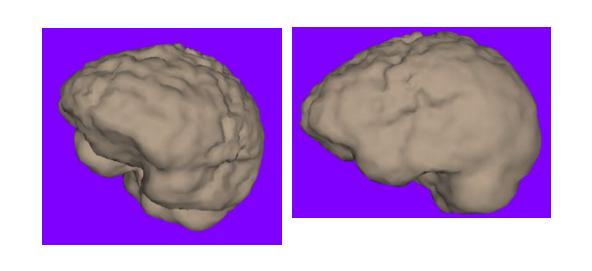
Figure 4 shows a rendering of a brain surface extracted using the methods discussed in this section.
Step 4, Selecting brain voxels
This algorithm selects in two phases those voxels that are inside or on the triangle mesh that represents the surface of the brain. The first phase makes a pass over the triangles in the mesh. Each triangle is rasterized in the 3D voxel grid. The rasterization is done three times in the coordinate directions. The idea for a given direction is to cast rays in that direction and find voxels that are approximately on or near the triangle. The final result of all the rasterization is a surface that is a few voxels thick. More important is that it is a closed surface.
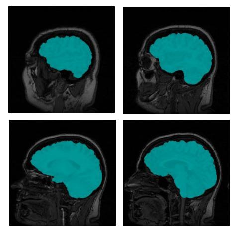
The end result is a ternary 3D image whose voxels are 0 for background, 1 for surface, and 2 for interior. The distinction between the surface and interior voxels allows an application to color the surface voxels in image slices to see how accurate the segmentation is. Figure 5 shows a few slices of the original MRI with the brain voxels colored.
Image types
You can apply this algorithm only to 3D MRI images.
Special notes
You can save the triangle mesh in the sur format that the level surface viewer supports. This allows you to render the extracted surface. The code also gives you access to the ternary mask image to do with as you please.
Reference
Refer to the following reference for more information about this algorithm:
Smith, Stephen. BET: Brain Extraction Tool. FMRIB Technical Report TR00SMS2, Oxford Center for Functional Magnetic Resonance Imaging of the Brain, Department of Clinical Neurology, Oxford University, Oxford, England.
Applying the Extract Brain Surface algorithm
To use this algorithm, do the following:
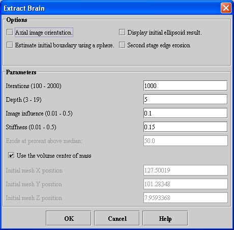
- Select Algorithms > Extract Brain. The Extract Brain dialog box opens.
- Complete the information in the dialog box.
- Click OK. The algorithm begins to run, and a progress bar appears with the status. When the algorithm finishes running, the progress bar disappears, and the results replace the original image.
|
Axial image orientation
|
Specifies that the image is in the axial orientation. Unless you first change the default values of the Initial mesh position boxes, marking or clearing this check box changes their values.
|
|
Estimate initial boundary using a sphere
|
Uses a sphere shape instead of an ellipse for estimating the initial boundary. Unless you first change the default values of the Initial mesh position boxes, marking or clearing this check box changes their values.
|
|
Display initial ellipsoid result
|
Displays the ellipsoid sphere to be used in extracting the brain. This option allows you to verify that the initial ellipsoid sphere correctly covers the area in the image where the brain is located.
|
|
Second stage edge erosion
|
Performs erosion process at the edge of the brain to remove nonbrain voxels. When you select this check box, the Erode at percent above median text box is enabled.
|
|
Iterations
|
Specifies the number of times to run the algorithm when evolving the ellipsoid into the brain surface. The default is 1000.
|
|
Depth
|
Specifies the maximum depth inside the surface of the brain to use in sampling intensities. The default value is 5.
|
|
Image influence
|
Controls the surface evolution by sampling to the specified depth to calculate the maximum and minimum intensities. The default value is 0.10.
|
|
Stiffness
|
Controls the stiffness of the mesh against motion in the surface normal direction. The default value is 0.15.
|
|
Erode at percent above median
|
Removes voxels (nonbrain material) that are at the edge of the segmentation and that have an intensity above the percent of the median voxel intensity of the brain. Type the appropriate percentage in this text box. This text box is enabled when you select Second stage edge erosion.
|
|
Use the volume center of mass
|
Contructs the mesh using the volume center of mass. When you select this check box, you cannot specify the Initial X, Y, or Z mesh positions.
|
|
Initial mesh 'X' position
|
Constructs the mesh using the X position that you specify. To specify a value for this text box, clear Use the volume center of mass. Unless you first change the default value of this box, marking or clearing either the Axial image orientation or Estimate initial boundary using a sphere check boxes changes the default value.
|
|
Initial mesh 'Y' position
|
Constructs the mesh using the Y position that you specify. To specify a value for this text box, clear Use the volume center of mass. Unless you first change the default value of this box, marking or clearing either the Axial image orientation or Estimate initial boundary using a sphere check boxes changes the default value.
|
|
Initial mesh 'Z' position
|
Constructs the mesh using the Z position that you specify. To specify a value for this text box, clear Use the volume center of mass. Unless you first change the default value of this box, marking or clearing either the Axial image orientation or Estimate initial boundary using a sphere check boxes changes the default value.
|
|
OK
|
Applies the algorithm according to the specifications in this dialog box.
|
|
Cancel
|
Disregards any changes that you made in the dialog box and closes this dialog box.
|
|
Help
|
Displays online help for this dialog box.
|
