Summary
This section provides information on and discusses how to use the following two FRET algorithms:
- FRET Bleed Through algorithm
- FRET Efficiency algorithm
Note: Only one user-selected color can be used from a color image.
Used consecutively, the FRET Bleed Through algorithm uses two sets of three 2D images and the FRET Efficiency algorithm uses one set of three 2D images to measure effects dependent on the proximity of fluorescent-labeled molecules.
You must first run the FRET Bleed Through algorithm twice: once on acceptor-dyed images and once on donor-dyed images. Using the results achieved from running this algorithm, you then use the FRET Efficiency algorithm to process images that were dyed with both the donor and acceptor dyes to obtain the FRET efficiency.
Image Types
Both algorithms could be applied to 3 2D images.
Background
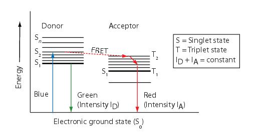
Fluorescent resonance energy transfer (FRET) refers to the non-radiative transfer of energy from an excited fluorochrome, called a donor, to a nearby fluorescent molecule, called an acceptor. The FRET technique measures the fluorescence signals of the donor, the acceptor, and the FRET signal. If FRET occurs, the donor channel signal is quenched and the acceptor channel signal is sensitized or increased.
The energy transfer efficiency E is conventionally defined as the number of energy transfer events divided by the number of photons absorbed by the donor, is related to the distance R between the acceptor and donor by:
where R_0, the Forster critical distance, is the distance at which E = 0.5.
Because FRET falls off as the sixth power of the distance between the donor and the acceptor, virtually no FRET occurs for distances greater than . Since is on the order of 10 to 70 Angstroms, by performing FRET measurements it is possible to distinguish proteins that are merely nearby in the same compartment from those proteins that are interacting with each other. Virtually no FRET occurs for distances that are greater than .
Figure below schematically illustrates the process of fluorescence and FRET. When a fluorescent molecule (donor) is excited (using a blue photon in this example), the molecule goes into an excited state (S1) for a few nanoseconds. During this time the molecule loses some of its energy after which it returns to the ground state (S0) by emission of a less energetic photon (green photon in this example). If another fluorescence molecule (acceptor), which is excited by green photons and emits red photons, is very close by, then it is likely that the donor non-radiatively transfers its excitation energy to the acceptor and returns to the ground state without emitting a photon. As a consequence, the acceptor becomes excited and later returns to the ground state by giving off a photon of lower energy (red photon in this example).
Measuring FRET using the sensitized emission method requires three sets of 2D images. You must first run the FRET Bleed Through algorithm once on three donor dye only images and once on three acceptor dye only images. You then run the FRET Efficiency algorithm on three images with both donor and acceptor dyes.
These images are:
- Image donor and/or acceptor dyes taken with a donor filter
- Image with donor and/or acceptor dyes taken with a FRET filter
- Image with donor and/or acceptor dyes taken with an acceptor filter
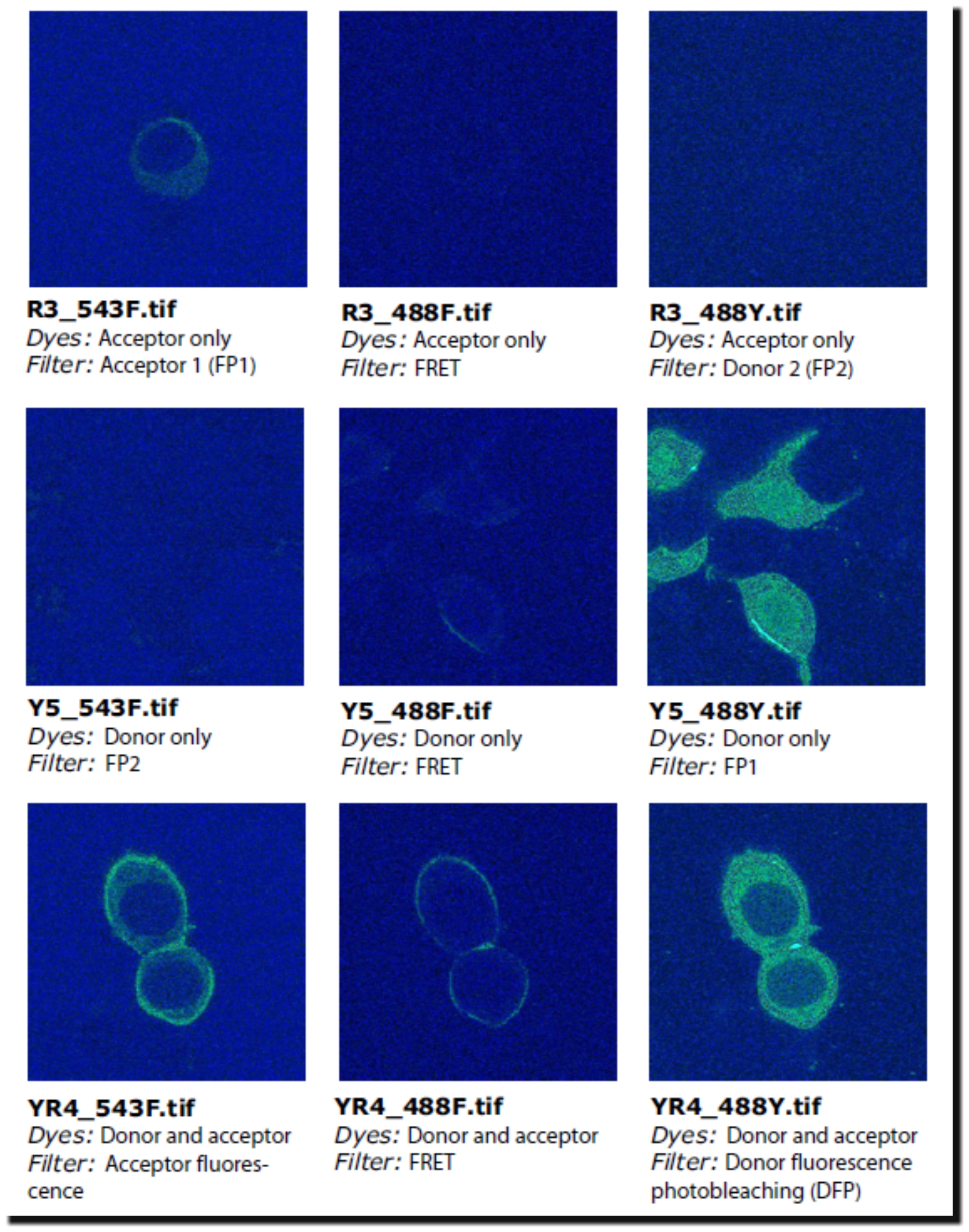
To obtain FRET efficiency, you need, therefore, a set of nine images. The table below and Figure: NIne images ... list and show the images that are used as examples in this discussion.
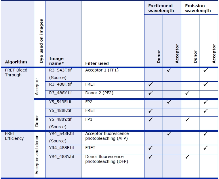
FP stands for "fluorescence protein". The term "FP1 filter" refers to the pair of filters normally used to acquire an image of fluorescence protein 1 (FP1). The pair of filters consists of an excitation filter and an emission filter. In order to measure bleed through, it is necessary to image each of the proteins (1 and 2) with the correct filters (1 and 2), wrong filters (i.e., 2 and 1), as well as image each of the proteins with the FRET filter. The FRET filter uses the excitation filter for the donor protein and the emission filter for the acceptor protein. For the bleed-through calculations I avoided using the terms "donor" and "acceptor" and instead use "1" and "2" since the donor and acceptor are used equivalently for the bleed through calculations. In the second part of the calculation to calculate the FRET efficiency, it does make a difference which is the donor and which is the acceptor, therefore I use the terms DFP and AFP.
FRET Bleed Through Algorithm
The FRET Bleed Through algorithm requires the six types of images listed in the Table below. You need to run the algorithm twice: Once on the set of three images with acceptor dye only (the first three images listed in the table); and once on the set of three images with donor dye only (the last three images listed in the table).
Sets of images |
Example image* |
Type of image |
|---|---|---|
Acceptor only dyed images |
R3_543F.tif |
An acceptor only dyed image taken with an acceptor filter set<a name="wp1029924"> </a> |
R3_488F.tif |
An acceptor only dyed image taken with a FRET filter set |
|
R3_488Y.tif |
An acceptor only dyed image taken with a donor filter set |
|
Donor only dyed images |
Y5_543F.tif |
An donor only dyed image taken with an acceptor filter set |
Y5_488F.tif |
An donor only dyed image taken with a FRET filter set |
|
Y5_488Y.tif |
A donor only dyed image taken with a donor filter set |
|
*Refer to the figure above to view these example images.
| ||
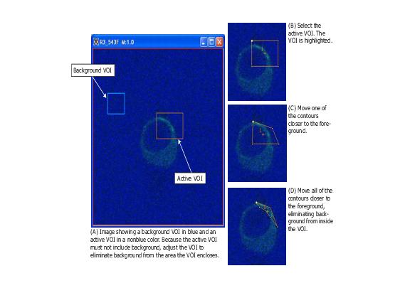
For both the acceptor dye only run and the donor dye only run, you need to create two or more VOI regions on the source image:
- A background VOI-The background region should have a smaller average intensity than the active region. Background VOIs appear in blue.
- One or more active VOIs-The area of the active regions are used for the bleed through calculations. Each different active VOI appears in a different nonblue color.
Caution: Do not use blue as an active VOI color.
You must create all of the VOIs on the source image, and the source image must be an image of the FP1 dye taken with a FP1 filter. That is, the source image must be either:
- An image with donor dye only taken with a donor fluorescent filter set
- An image with acceptor dye only taken with an acceptor fluorescent filter set
- Note: Pixels that are saturated in any of the three images are excluded from all calculations.
Performing the Acceptor dye only run
Running the algorithm on images in which only the acceptor dye was used obtains the following values for each active VOI region:
- AFP (acceptor fluorescence photobleaching) to FRET bleed through value
- AFP to DFP (donor fluorescence photobleaching) bleed through value
The algorithm displays these values in the Output window.
Performing the Donor dye only run
Running the algorithm on a set of three images in which only the donor dye was used obtains the following values for each active VOI region, which are displayed in the Output window:
- DFP to FRET bleed through value
- DFP to AFP bleed through value
These values are displayed in the Output window.
Moving to FRET Efficiency
Once the four bleed through parameters (AFP to FRET bleed through, AFP to DFP bleed through value, DFP to FRET bleed through, and DFP to AFP bleed through) are obtained, you can then run the FRET Efficiency algorithm. You run the FRET Efficiency algorithm on the last set of three images in Figure: NIne images .... This last set of images contain both donor and acceptor dyes.
Calculating the FRET and FP2 values
The FRET Bleed Through algorithm calculates the FRET and FP2 values using the following equations:
- denom = mean(FP1 dye with FP1 filter active VOI) - mean (FP1 dye with FP1 filter background VOI)
- FRET bleed through = [mean(FP1 dye with FRET filter active VOI) - mean (FP1 dye with FP2filter background VOI]/denom
- FP2 bleed through = [mean (FP1 dye with FP2 filter active VOI) - mean (FP1 dye with FP2 filter background VOI)]/ denom
Applying the FRET Bleed Through algorithm
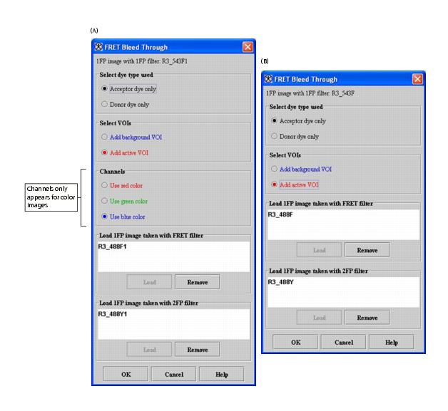
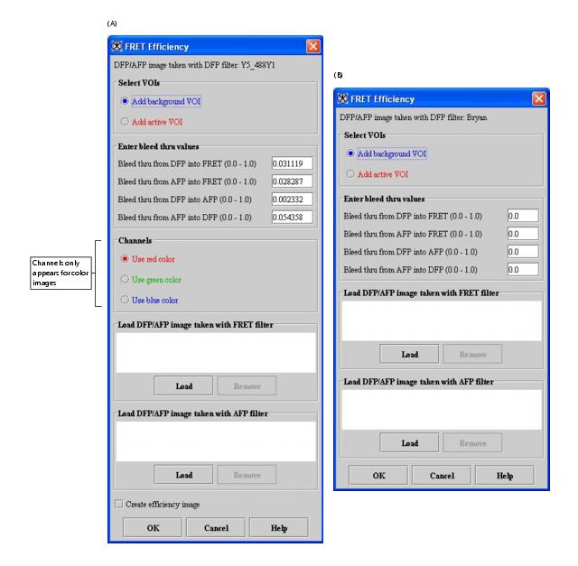
Note: If images on which you're running the algorithm are in color, the FRET Bleed Through dialog box with color options will appear. This dialog box includes a Channels group, which allows you to select the color channel on which to run the algorithm. If the images are in grayscale, the Channels group does not appear.
The images used in the following instructions are the ones listed in Table 3 and shown in the first two rows in Figure: Nine images ....
Performing the acceptor dye only run
To run this algorithm, do the following:
- Select File > Open to open the image file on which the acceptor dye and FP1 filter were used (example image: R3_543F.tif in Figure: NIne images ...) (this image is the source image).
- Select Algorithms > Microscopy > FRET Bleed Through.
- The FRET Bleed Through dialog box opens.
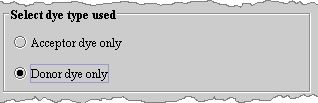
- Select Acceptor dye only in Select dye type used.
- Select Add background VOI in Select VOIs.
- Create a background VOI using the ellipse VOI , rectangle VOI , levelset VOI , or polyline VOI on the image in the background of the image. This VOI appears in blue.
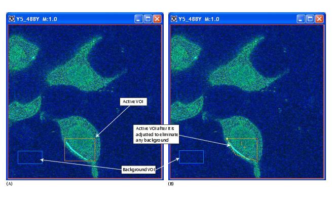
- Select Add active VOI in Select VOIs.
- Create an active VOI using the ellipse VOI , rectangle VOI , levelset VOI , or polyline VOI in the foreground of the image, and adjust the contours of the VOI to eliminate any image background. This VOI appears in a non-blue color.
- Decide whether to create additional active VOIs. If you decide against creating additional active VOIs, go to the next step.
- If you decide to create additional active VOIs, do the following: 1) Select , the New VOI icon; 2)Create another active VOI using the ellipse VOI , rectangle VOI , levelset VOI , or polyline VOI , and adjust the contours of the VOI to eliminate any image background. This VOI appears in a nonblue color that is different from the color of the first active VOI.
Note: If you do not select , the New VOI icon, MIPAV creates additional contours of the same color for the first active VOI and sums all areas within the contours of this VOI together.
- Select Use red channel, Use green channel, or Use blue channel in Channels. Remember: The Channels group only appears if the source image is in color.
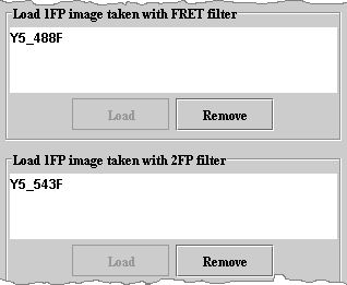
- Click Load under Load 1FP image taken with FRET filter box. The Open Image dialog box appears.
- Navigate to the directory where the image (example image: R3_488F.tif) is stored, and select the image. (Refer to Figure: NIne images ... to see this image.)
- Click Open. The name of the image appears in the Load 1FP image taken with FRET filter box.
Note: The Remove button only becomes enabled when an image appears in the box.
- Click Load under the Load 1FP image taken with 2FP filter box. The Open Image dialog box (Figure 81) appears.
- Navigate to the directory where the image (example image: R3_488Y.tif) (refer to Figure: Nine images ... to see this image) is stored, and select the image.
- Click Open. The name of the image appears in the Load 1FP image taken with 2FP filter box.
- Click OK. The algorithm begins to run. When the algorithm finishes, it places the data in the Output window.
Performing the donor dye only run
- Select File > Open to open the image file on which the donor dye and FP2 filter were used (example image: Y5_488Y.tif in Figure: Nine images ...) (this image is the source image).
- Select Algorithms > Microscopy > FRET Bleed Through. The FRET Bleed Through dialog box opens.
- Select Donor dye only in Select dye type used.
- Select Add background VOI in Select VOIs.
- Create a background VOI using any of the following options: the ellipse VOI , rectangle VOI , levelset VOI , or polyline VOI on the image in the background of the image. This VOI appears in blue.
- Select Add active VOI in Select VOIs.
- In the foreground of the image, create an active VOI using any of the VOI options (the ellipse VOI, rectangle VOI, levelset VOI, or polyline VOI) and adjust the contours of the VOI to eliminate any image background. This VOI appears in a nonblue color. Decide whether to create additional active VOIs.
- If you decide against creating additional active VOIs, go to the next step. If you decide to create additional active VOIs, do the following: 1) Select,the New VOI icon. 2) Create another active VOI using the ellipse VOI , rectangle VOI , levelset VOI , or polyline VOI , and adjust the contours of the VOI to eliminate any image background. This VOI appears in a non-blue color that is different from the color of the first active VOI.
Note: The New VOI icon, MIPAV creates additional contours of the same color for the first active VOI and sums all areas within the contours of this VOI together.
- Select Use red channel, Use green channel, or Use blue channel in Channels if the images are in color. Remember: The Channels group only appears if the source image is in color.
- Click Load under Load 1FP image taken with FRET filter box. The Open Image dialog box appears.
- Click Load under the Load 1FP image taken with 2FP filter box. The Open Image dialog box appears.
- Navigate to the directory where the image (example image: Y5_543F.tif) is stored, and select the image. The name of the image appears in the Load 1FP image taken with 2FP filter box.
- Click OK. The algorithm begins to run. When the algorithm finishes, it places the data in the Output window
FRET Bleed Through dialog box
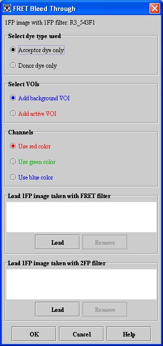
Select dye type used
Acceptor dye only-The dye used on images that are processed through the acceptor-dye run of the FRET Bleed Through algorithm. As a result of this run, the algorithm calculates the AFP to FRET bleed through value and the AFP to DFP bleed through value.
Donor dye only-The dye used on images that are processed through the donor dye only run of the FRET Bleed Through algorithm. During this run, the algorithm calculates the DFP to FRET bleed through value and the DFP to AFP bleed through value.
Select VOIs
Add background VOI-Indicates a region in the image that is the background. Using the ellipse VOI, rectangle VOI, levelset VOI, or polyline VOI, you may create one background VOI. The background VOI appears in blue.
Add active VOI-Indicates one or more regions in the image that are in the foreground. You may create the first active VOI using the ellipse, rectangle, levelset, or polyline VOI. To create additional active VOIs, first select New VOI and then select ellipse, rectangle, levelset, or polyline VOI. Each active VOI appears in a different, nonblue color.
Channels
- Use red color-Selects the red channel for the FRET analysis.
- Use green color-Selects the green channel for the FRET analysis.
- Use blue color-Selects the blue channel for the FRET analysis.
Load FP1 image taken with FRET filter
Lists the FRET filtered image that you selected after clicking Load.
Load
Allows you to load an FP1 image that was taken with the FRET filter. Clicking this button causes the Open Image dialog box-from which you can select an image-to appear.
Remove
Removes the image that is selected in the Load FP1 image taken with FRET filter box.
Load FP1 image taken with FP2 filter
Lists the FP2 filtered image that you selected after clicking Load.
Load
Allows you to load an FP1 image that was taken with the FP2 filter. Clicking this button causes the Open Image dialog box-from which you can select an image-to appear.
Remove
Removes the image that is selected in the Load FP2 image taken with FP2 filter box.
OK
Applies the algorithm according to the specifications in this dialog box.
Cancel
Disregards any changes that you made in this dialog box and closes the dialog box.
Help
Displays online help for this dialog box.
FRET Efficiency algorithm
The FRET Efficiency algorithm uses the four bleed through parameters obtained from running the FRET Bleed Through algorithm. It requires a set of three images:
Sets of images |
Example image* |
Type of image |
|---|---|---|
Donor and acceptor dyed images |
YR4_543F.tif |
An acceptor- and donor-dyed image taken with an acceptor filter set |
YR4_488F.tif |
An acceptor- and donor-dyed image taken with a FRET filter set |
|
YR4_488Y.tif |
An acceptor- and donor-dyed image taken with a donor filter set |
|
*Refer to Nine Images figure to view these example images. |
||
- Donor- and acceptor-dyed image taken with a donor fluorescence photobleaching (DFP) filter
- Donor- and acceptor-dyed image taken with a FRET filter
- Donor- and acceptor-dyed image taken with an acceptor fluorescence photobleaching (AFP) filter
The algorithm assumes the presence of two or more VOI regions on the source image:
A background VOI-The background region has a smaller average intensity than the active region. Background VOIs appear in blue. One or more active regions-The area of the active regions, or VOIs, are used for the efficiency calculations. Each different active VOI appears in a different nonblue color.
Caution: Do not use blue as an active VOI color.
Note: Pixels with saturation values in any of the three images are excluded from all calculations.
For each active VOI region, this algorithm outputs the FRET efficiency and the adjusted donor and adjusted acceptor intensities.
Applying the FRET Efficiency algorithm
Note: The images used in the following instructions are the ones listed in Table 3 and shown in the first two rows in Figure: Nine images ....
To use the FRET Efficiency algorithm, do the following:
- Select File > Open to open the image file on which both the acceptor dye and donor dyes were used and DFP filter were used (example image: YR4_488Y.tif).
- Select Algorithms > Microscopy > FRET Efficiency. The FRET Efficiency dialog box (Figure 91) opens.
- Select Add background VOI in Select VOIs on the FRET Efficiency dialog box.
- Create a background VOI on the image in the background of the image. This VOI appears in blue lines.
- Select Add active VOI in Select VOIs on the FRET Efficiency dialog box.
- Create an active VOI using the ellipse VOI , rectangle VOI , levelset VOI , or polyline VOI in the foreground of the image, and adjust the contours of the VOI to eliminate any image background. This VOI appears in a nonblue color (Figure 86).
- Decide whether to create additional active VOIs.
- If you decide against creating additional active VOIs, go to the next step. If you decide to create additional active VOIs, do the following: 1)select , the New VOI icon; 2) create another VOI using the ellipse VOI , rectangle VOI , levelset VOI , or polyline VOI , and adjust the contours of the VOI to eliminate any image background. This VOI appears in a nonblue color that is different from the color of the first active VOI.
Note: If you do not select , the New VOI icon, MIPAV creates additional contours of the same color for the first active VOI and sums all areas within the contours of this VOI together.
Note: MIPAV prefills the Enter bleed through values. However, if the correct bleed through values are not automatically entered, type them into the fields.
- Click Load under Load DFP/AFP image taken with FRET filter box. The Open Image dialog box appears.
- Navigate to the directory where the image (example image: YR4_488F.tif) is stored, and select the image.
- Click Open. The name of the image appears in the Load DFP/AFP image taken with FRET filter box.
Note: The Remove button becomes enabled when an image appears in the box.
- Click Load under the Load DFP/AFP image taken with AFP filter box. The Open Image dialog box appears.
Navigate to the directory where the image (example image: YR4_543F.tif) is stored, and select the image. The name of the image appears in the Load DFP/AFP image taken with AFP filter box.
- Click OK. MIPAV places the data from this second part of the procedure in the Output window.
FRET Efficiency dialog box
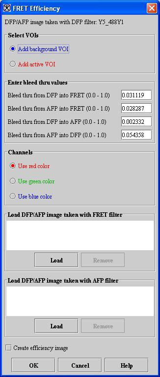
Select VOIS
Add background VOI-Indicates a region in the image that is the background, which has a smaller average intensity than the active region. Using the ellipse VOI, rectangle VOI, levelset VOI, or polyline VOI, you create a background VOI. The background VOI appears in blue.
Add active VOI-Indicates one or more regions in the image that are in the foreground. You may create the first active VOI using the ellipse VOI, rectangle VOI, levelset VOI, or polyline VOI. To create more active VOIs, select New VOI. Each different active VOI appears in a different nonblue color.
Bleed through from DFP into FRET (0.0-1.0)
Indicates the bleed through value from DFP into FRET.
Bleed through from AFP into FRET (0.0-1.0)
Indicates the bleed through value from AFP into FRET.
Bleed through from DFP into AFP (0.0-1.0)
Indicates the bleed through value from DFP into AFP.
Bleed through from AFP into DFP (0.0-1.0)
Indicates the bleed through value from AFP into DFP.
Channels
- Use red color-Selects the red channel.
- Use green color-Selects the green channel.
- Use blue color-Selects the blue channel.
Load DFP/AFP image taken with FRET filter
Lists the FRET filtered image that you selected after clicking Load.
Load
Allows you to load a DFP/AFP image that was taken with the FRET filter. Clicking this button causes the Open Image dialog box-from which you can select an image-to appear.
Remove
Removes the image that is selected in Load DFP/AFP image taken with FRET filter.
Load DFP/AFP image taken with AFP filter
Lists the AFP filtered image that you selected after clicking Load.
Load
Allows you to load a DFP/AFP image that was taken with the AFP filter. Clicking this button causes the Open Image dialog box-from which you can select an image-to appear.
Remove
Removes the image that is selected in Load DFP/AFP image taken with AFP filter.
OK
Applies the algorithm according to the specifications in this dialog box.
Cancel
Disregards any changes that you made in this dialog box and closes this dialog box.
Help
Displays online help for this dialog box.
References
- Both algorithms port the MATLAB routines provided by Dr. Stephen Lockett.
- Gordon, Gerald W., Gail Berry, Xiao Huan Liang, Beth Levine, and Brian Herman. "Quantitative Fluorescence Resonance Energy Transfer Measurements Using Fluorescence Microscopy." Biophysical Journal 74(May 1998):2702-2713.
- Kenworthy, Anne K. "Imaging Protein-Protein Interactions Using Fluorescence Energy Transfer Microscopy." Methods, 24(2001):289-296.