The Manual 2D Series algorithm allows you to manually or semi manually register two 2D grayscale or color images by placing corresponding points on both images, and then applying either the Landmark-Thin Plate Spline or Landmark-Least Squares algorithm. After applying one of these algorithms, you can then, if needed, use the other algorithm. In addition, at any time, you can manually adjust the alignment of each image.
The algorithm also lets you manually register different slices of a 2.5D and 3D image datasets in the same way as 2D images. See also Applying the Manual 2D Series algorithm to 2.5D images and Applying the Manual 2D Series algorithm to 3D images.
Background
Through the Registration: Manual 2D Series dialog (Figure 1), this algorithm provides the tools for manually registering images, as well as the ability to use two of the landmark registration algorithms-Thin Plate Spline and Least Squares.
The following tools are available for manually registering images:
- Changing displaying proportion
- Moving the adjusted image
- Rotating the adjusted image
- Delineating the landmark points
- Applying the image registration algorithms
Image types
You can apply this algorithm to 2D, 2.5 D, and 3D grayscale and color images. The dimensions or image type of the adjusted image need not be the same as the dimensions or image type of the reference image. The adjusted image has the same image type and the same extents as the reference image. See also: Applying the Manual 2D Series algorithm on 2D images, Applying the Manual 2D Series algorithm to 2.5D images, and Applying the Manual 2D Series algorithm to 3D images.
Special notes
For 2D, 2.5D and 3D images, three or more landmark points are required. The algorithm may fail if nearly all of the points fall on the same line.
References
"Least-Squares Fitting of Two 3-D Point Sets" by K.S. Arun, T.S. Huang, and S.D. Blostein, IEEE Transactions on Pattern Analysis and Machine Intelligence, Vol. PAMI-9, No. 5, September, 1987, pp. 698-700.
David Eberly, "Thin Plate Splines" of Magic Software at http://www.magic-software.com. Also at the same site are the files: MgcInterp2DThinPlateSpline.h, MgcInterp2DThinPlateSpline.cpp, MgcInterp3DThinPlateSpline.h, MgcInterp3DThinPlateSpline.cpp Paper that explains warping from one x,y source to another x,y target set.
Fred L. BookStein, "Principal Warps: Thin-Plate Splines and the Decompositions of Deformations," IEEE Transactions on Pattern Analysis and Machine Intelligence, Vol. 11, No. 6, June 1989, pp. 567-585.
Applying the Manual 2D Series algorithm on 2D images
To run this algorithm, complete the following steps:
- Open two images- the reference image and the image you want to register or adjusted image.
- Select the reference image.
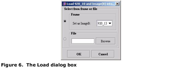
- Select Algorithms > Registration > Manual 2D Series. The Load dialog box appears. See Figure 1.
- Select the image that you want to register to the reference image. Note that, if only two images are open, the Set as Image B box automatically selects the other open image-the one you did not select-as Image B or adjusted image. See Figure 1.
- To select a different image, select the File option, and then click Browse to find and open another image.
- Click OK.
- The Manual 2D Series window opens. By default, the window opens in Blended mode. Note that, opening this window automatically corrects image resolution and scaling.
As shown in Figure 2, the Registration: Manual 2D Series window has the main menu (see below) and two tabs: Blended and Dual. Refer to "Blended tab" and "Dual tab".
|
File
|
Close Registration
|
Closes this dialog without saving the images.
|
|
Show VOIs in blended window
|
On the Blended tab, displays the VOIs that you've delineated on the Dual tab.
| |
|
Thin plate spline for intensity
|
Uses the Thin Plate Spline algorithm for calculating intensity values. See also [RegistrationLandmarkTPSpline.html#wp1275364 "Registration: Landmark-TPSpline"].
| |
|
Help
|
Runs help for this dialog box.
|
Blended tab
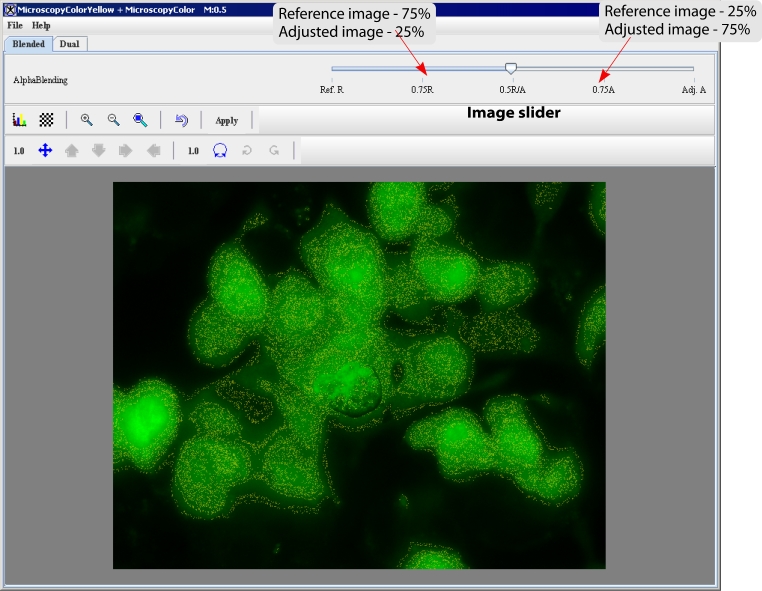
The Blended tab shows both images: the adjusted image superimposed on top of the reference image. By default, the image frame shows both images blended in proportion 50/50.
Changing displaying proportion
You can use the AlphaBlending image slider to change the displaying proportion towards either increasing the amount of the reference image (the Ref.R side of the slider) or adjusted image (the Adj.A side of the slider) displayed. The image slider is located at the top of the Blended tab. See also Figure 3 and Section: "Moving and rotating the adjusted image".
 |
The Blended tab options:
|
|
Opens the Lookup table dialog box. For the Lookup table (LUT) dialog box options, refer to MIPAV User's Guide, Volume 1, Basics, Look-up Table window. See also Using LUT to arrange the images.
|
 |
|
|
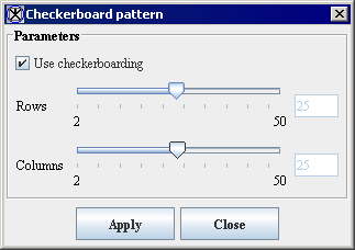
The checkerboard tool displays both portions of both images in an alternating fashion, much like the squares on a checkerboard. Portions of the reference image (Image A) appear where the light-colored squares would appear on the checkerboard; portions of the adjusted image (Image B) appear in place of the dark-colored squares. You can use the Checkerboard pattern dialog box options to adjust the number of rows and columns displayed. See also MIPAV User's Guide, Volume 1, Basics, for more infromation about the checkerboard tool.
|
  |
|
|
Magnifies the images 2xn times.
| |
|
|
Magnifies the images 0.5xn times; or minifies the images 2xn times, which is the same.
| |
|
|
Displays the window filled only with the adjusted image (Image B) over the reference image. You can use this window to look at the alignment of details in the images.
|
 |
|
|
Restores image to its original state. This icon also deletes all landmark points on the reference image and on the adjusted image. If the Apply button has already been selected, the Reset icon undoes all changes that occurred since the last time the Apply button was selected.
| |
|
Apply
|
Commits the changes that you made to the images, but it leaves the window open for you to make further changes, if desired.
| |
|
|
Activates moving mode by making the moving icons available. The moving icons or the icons that display direction arrows let you move the adjusted image in one direction only by a specified number of pixels. The default number of pixels is 1; however, the number of pixels may be from 0.01 to 2048.0. Therefore, the direction arrows provide the greatest specificity in moving the image, which is perfect for fine adjustments. To change the number of pixels, click the Set pixel increment icon; enter a desired number in the Pixel Increment box; and then click Apply. Refer to Moving and rotating the adjusted image.
| |
|
|
Activates rotation mode. If the rotation of the adjusted image is incorrect, you can change the rotation of the image with the two rotation icons: Rotate clockwise and Rotate counterclockwise. Rotation icons allow you to turn the adjusted image in the desired direction only by a specified degree (1-360). The default degree is 1, and it is shown next to the Rotate Image icon. To change the degree, click the Change Degree Increment icon; enter a desired number in the Degree Increment box; and then click Apply. Refer to Moving and rotating the adjusted image
| |
Moving and rotating the adjusted image
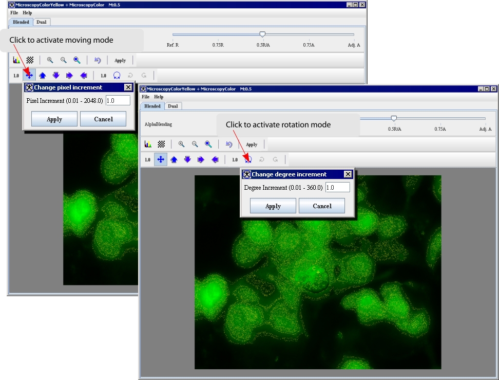
Figure 5 shows the icons which allow you to move the adjusted image in all directions or specifically up, down, left, and right a certain number of pixels. You can also rotate the adjusted image clockwise or counterclockwise. Note that all these tools are available only on the Blended tab.
To activate moving mode, click on the Translate image icon first, and then use the arrow icons to move the adjusted image in desired direction. You can also set up the moving increment (in pixels). Current increment is shown next to the Translate image icon. Refer to Figure 5.
To activate rotation mode, click on the Rotate Image icon, and then use the Rotate Clockwise or Rotate Counterclockwise icons to rotate the image. You can also set up the rotation increment (in grades). Current increment is shown next to the Rotate Image icon.
 |
Moving the adjusted image
The Translate image icon activates moving mode for the adjusted image and allows you to move the image in any direction. This icon only appears on the Blended tab, which is where all manual adjustments to image registration occurs. To move the adjusted image, click Translate Image and, holding down the left mouse button, drag the icon in the direction in which you wish to move the image, and then release the mouse button. After a few moments, the image appears in the new position. Note that, depending on where you moved the adjusted image, its outer portions may disappear beyond the outer edges of the reference image. In this case, you can use the same icon to move the adjusted image again.
Moving the adjusted image with the direction arrows
The icons that display direction arrows let you move the adjusted image in one direction only by a specified number of pixels. The default number of pixels is 1; however, the number of pixels may be from 0.01 to 2048.0. Therefore, the direction arrows provide the greatest specificity in moving the image, which is perfect for fine adjustments.
To change the number of pixels, click the Set pixel increment icon; enter a number in the Pixel Increment box; and then click Apply. See Figure 5.
Rotating the adjusted image
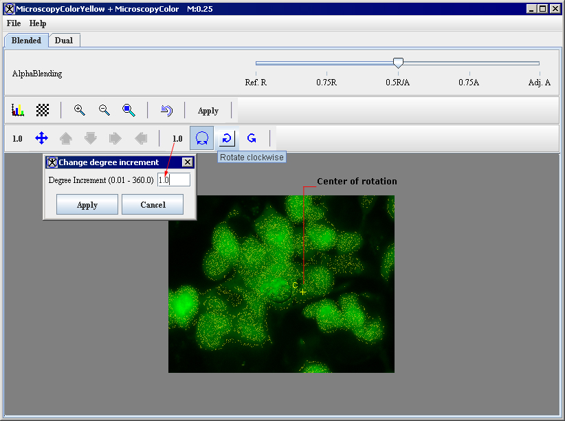
If the rotation of the adjusted image is incorrect, you can change the rotation of the image using the rotation icons as shown in as shown in Figure 6.
- To activate rotation mode, click the Rotate Image icon.
- Then, use the Set Degree Increment option to set up the desired degree increment. The increment's range is between 0.01 and 360.0 degrees.
- Select the center of rotation for the image. In order to do that, click Rotate Image, and then set the center by clicking with the mouse on the image. The letter C appears with a yellow crosshair cursor ( ). You can then drag a line from the center of rotation to move the image above or below the center of rotation.
- To rotate the image clockwise, click Rotate Clockwise; and to rotate the image counterclockwise, click Rotate Counterclockwise.
The image can also be rotated manually by dragging away from the center of rotation, and then dragging either clockwise of counterclockwise.
 |
|
|
Note: You can change the degree increment any time to achieve exact registration. |
Dual tab
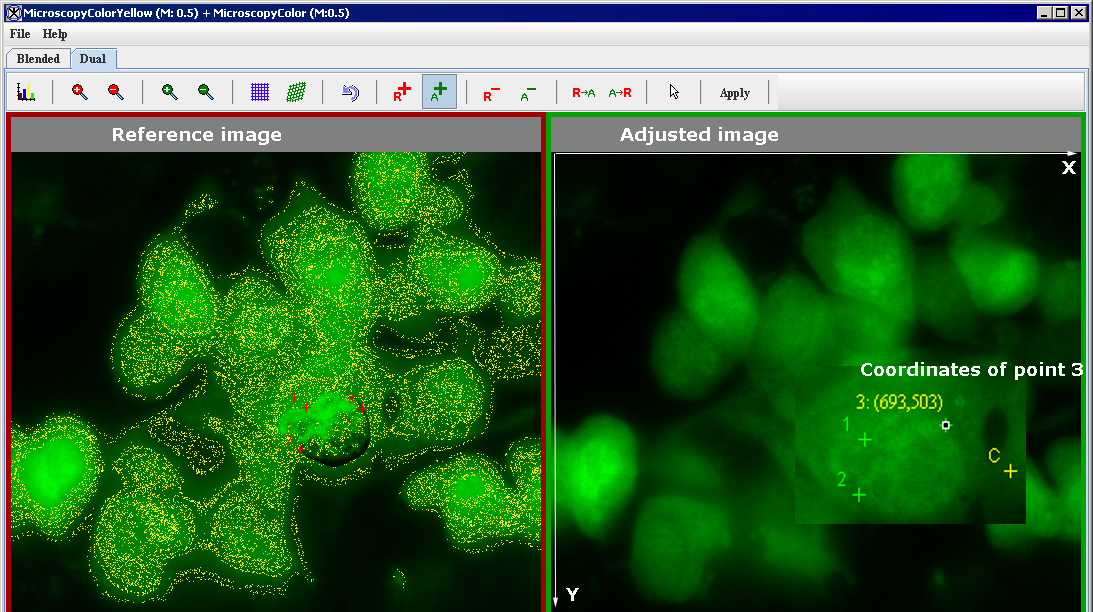
The Dual tab shows both the reference image and the adjusted image side by side in the image area at the bottom of the page.
Note that the border around the reference image, the image on the left side of the page, appears in red. The border around the adjusted image, which is on the right side of the page, appears in green. Several of the icons near the top of the page are color coded to the images. That is, the red icons apply to the reference image, and the green icons apply to the adjusted image.
The Dual tab offers the following options
|
Blended tab
|
Displays the Blended page, which shows the image to be registered superimposed on the reference image. This page allows you to move and align the image to be registered with the reference image. For the Blended tab options refer to Figure 7.
| |
|
Dual tab
|
Displays the Dual page, which shows each image side by side, and allows you to delineate three or more landmarks on each image before you apply the Landmark-Least Squares algorithm or the Landmark-Thin Plate Spline algorithm to the images.
| |
|
|
Displays the Lookup Table window, which includes two tabs: Image A, the reference image, and Image B, the image to be registered.
| |
|
|
Doubles the size of reference images, magnifying them to twice their current size. If an image is too large for the current window size, scroll bars appear, and you may need to manually adjust the size of the window. To restore reference images to their original size, use the Magnify Reference Image 0.5x icon, as many times as you used this icon.
| |
|
|
Reduces the magnification level of reference images in half. To restore reference images to their original size, use the Magnify Reference Image 2.0x icon, as many times as you used this icon.
| |
|
|
Doubles the size of adjusted images, magnifying them to twice their current size. If an image is too large for the current window size, scroll bars appear, and you may need to manually adjust the size of the window. To restore adjusted images to their original size, use the Magnify Reference Image 0.5x icon, as many times as you used this icon.
| |
|
|
Reduces the magnification level of adjusted images in half. To restore adjusted images to their original size, use the Magnify Reference Image 2.0x icon as many times as you used this icon.
| |
|
|
Applies the Landmark-Least Squares algorithm to the image to be registered. After the algorithm is applied, if needed, you can apply the Landmark-Thin Plate Splines algorithm on the image, or you can manually adjust the alignment of the image on the Blended page.
| |
|
|
Applies the Landmark-Thin Plate Spline algorithm to the image to be registered. After this algorithm is applied, if needed, you can apply the Landmark-Least Squares algorithm on the image, or you can manually adjust the alignment of the image on the Blended page.
| |
|
|
Restores the image to its original state. This icon deletes all points on the reference image and on the adjusted image. If the Apply button has already been selected, the Reset icon undoes all changes that occurred since the last time the Apply button was selected.
| |
|
|
Adds a landmark point to the reference image each time you click the left mouse button. Note that the points are sequentially labeled from 1 on in the order in which you created them. To remove points, return the cursor to its default mode by clicking [Manual2DSeriesOV.html#wp1855768 Return to default mode], select the point to be deleted, and then click the Delete Selected Reference Slice Markers icon.
| |
|
|
Adds a landmark point to the adjusted image each time you click the left mouse button. Note that the points are sequentially labeled from 1 to n in the order in which you created them. To remove points, return the cursor to its default mode by clicking [Manual2DSeriesOV.html#wp1855768 Return to default mode], select the point to be deleted, and click the Delete Selected Adjusted Slice Markers icon. Note: landmarks in the reference image should correspond to landmarks in the adjusted image.
| |
|
|
Removes the landmark point that you selected in the reference image. To remove a point, first return the cursor to its default mode by clicking [Manual2DSeriesOV.html#wp1855768 Return to default mode], then select the point to be deleted, and then click the Delete Selected Reference Slice Markers icon.
| |
|
|
Removes the landmark point that you selected in the adjusted image. To remove the point, first return the cursor to its default mode by clicking [Manual2DSeriesOV.html#wp1855768 Return to default mode], then select the point to be deleted, and finally click the Delete Selected Adjusted Slice Markers icon.
| |
|
|
Copies landmarks from the reference image to adjusted image. Note that landmarks which were copied to the adjusted image have the same x, y coordinates as the reference image landmarks.
| |
|
|
Copies landmarks from the adjusted image to reference image. Note that landmarks you copied to the reference image have the same x, y coordinates as the adjusted image landmarks.
| |
|
|
Returns the cursor to its default mode, which allows you to change from adding points to deleting points from the image.
| |
|
|
Commits the changes that you made to the images, but it leaves the window open for you to make further changes if desired.
| |
 |
Using the image registration algorithms
Before applying the Landmark-Least Squares algorithm or the Landmark-Thin Plate Spline algorithm to the images you must delineate three or more landmark points or landmarks on each image. See Figure 8.
Delineating the landmark points
To place landmarks on the reference image, click the Reference Slice Markers icon, and then click the mouse on the reference image where the landmark should be located. The landmark appears on the image in red type and is sequentially numbered. Create at least two more landmarks on the image.
To place landmarks on the adjusted image, click the Adjusted Slice Markers icon, and create at least three landmarks on the image by clicking the mouse. The landmarks, which are sequentially numbered, appear in green type.
To remove a landmark point from the reference or adjusted image, you need to return the mouse cursor to its default mode by clicking on the Return to Default Mode icon. You can then select the point by clicking on it with the mouse, and then delete it by clicking the corresponding Delete Selected Markers icon.
Applying the image registration algorithms
After you have delineated the landmark points on both images, select the Least Squares algorithm. The Least Squares algorithm registers the adjusted image to the reference image by using corresponding points placed in both images.
The Thin Plate Spline algorithm allows you to register two images in a nonlinear manner using the corresponding landmark points that you delineate in both images.
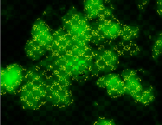
The program registers the images and the landmarks appear in yellow type followed by the specific positions in parentheses.
At this point, you should determine the following:
- Whether there is a need to make other manual adjustments to the registration. If so, return to the Blended tab and use the direction or the rotation icons. Use the Window region of image B icon to verify alignment. Refer to "making manual reconcilements to the adjusted image" .
- Whether to run the other algorithm. If so, simply call either the Least Squares or Thin Plate Spline algorithm, as appropriate.
- Whether to restore the adjusted image to its original form by clicking Reset.
- Whether to select Apply to keep changes made by the algorithm.
making manual reconcilements to the adjusted image
After you apply either the Least Squares or the Thin Plate Spline algorithm on the images, you may want to manually ascertain whether key portions of the reference image and the image to be registered, or adjusted image, are in alignment. One way of checking alignment, or registration, is using the Window region of image B icon. A recommended method for checking registration and for correcting it follows.
To check registration, do the following:
- Click Blended in the Manual 2D Series window to display the Blended page. Both the reference image and the image to be registered, or adjusted image, appear at the bottom of the window. The adjusted image is superimposed over the reference image.
- By default, the arrow on the AlphaBlending slider appears in the middle of the slider at 0.5R/A, which means that 50 percent of each image are shown on the page.
- Slide the arrow on the AlphaBlending slider all the way to the right until it reaches the label "Adj. A." This label indicates that 100 percent of the adjusted image is displayed on the page and, therefore, the reference image does not appear.
- Now, open Lookup table for the adjusted image. Note that the window includes two tabs: one for Image A, the reference image, and one for Image B, the adjusted image.
- Use the LUT options to change the intensity for one of the color channels for the adjusted image, for example, to increase the red channel. The purpose in doing this task is to easily distinguish the adjusted image from the reference image. Refer to "Using LUT to arrange the images".
- Return to the Blended tab of Manual 2D Registration dialog box and move the AlphaBlending Image slider arrow all the way to the left on the slider. The label "Ref. R" indicates that the page now displays 100 percent of the reference and does not display the adjusted image.
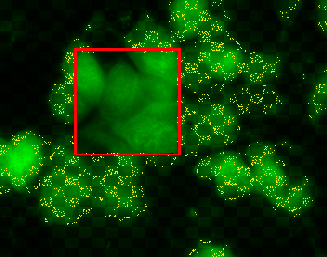
- Click the Window Region of Image B icon and position the cursor over the reference image. Notice that a square box appears on the image. The box is filled with the adjusted image, which is appears in pale red. You can use this box to look at the alignment of details in the images. See Figure 9.
 |
- Determine whether you want to correct the alignment of the images. If you do, there are several ways to align the adjusted image:
- Moving the image using the Translate image icon and direction arrows. See also "Moving the adjusted image".
- Rotating the image using the Rotate Image icon. See also "Rotating the adjusted image".
Using LUT to arrange the images
You can use the LUT options to distinguish the adjusted image from the reference image. In order to to that
- Return to Blended mode.
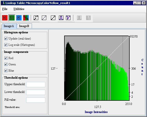
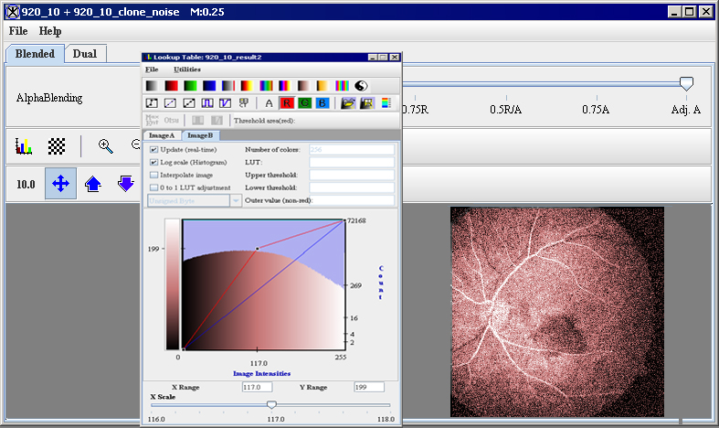
- Click the Lookup Table icon, to display the Lookup Table window. Note that the window includes two tabs: one for Image A - the reference image, and the other one for Image B - the adjusted image.
- For the adjusted image, drag the image intensity line for the red channel up in the middle. In this case, it creates a lighter colored red. The adjusted image now appears in pale red. Actually, you can change the color of the image to any color. See figure 10 below.
 |
|
|
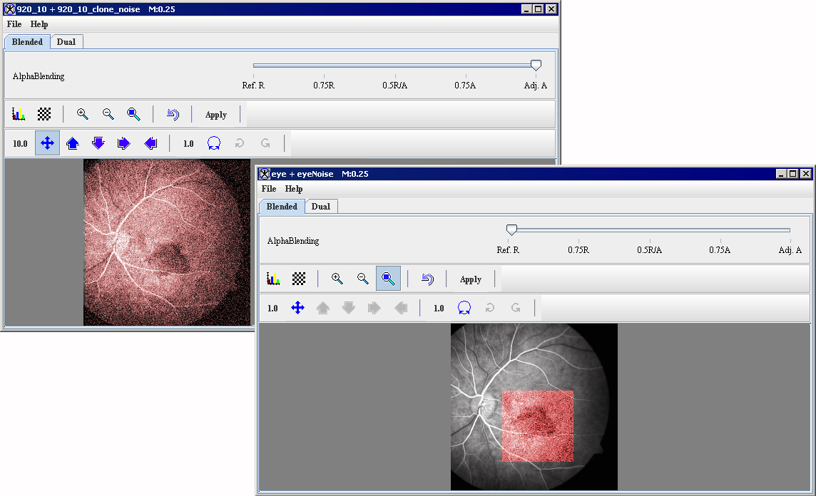
Tip:You may want to maximize the window and enlarge the images so that you can view details of the images while checking alignment. To maximize the window, simply click Restore. To maximize the image, click the Magnify image 2.0x icon, which magnifies the image to twice its current size, as many times as needed. |
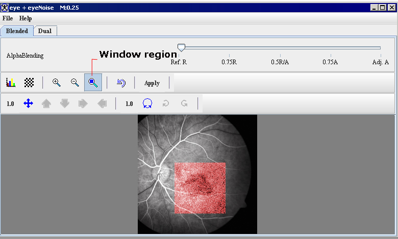
- Return to the Blended tab and move the image slider arrow all the way to the left on the slider, so the page now displays only the reference image.
- Click the Window Region of Image B icon and position the cursor over the reference image.
- The Windows Region box appears on the image, filled with the adjusted image, which is appears in pale red.
- Use this box to look at the alignment of details in the images.
 |
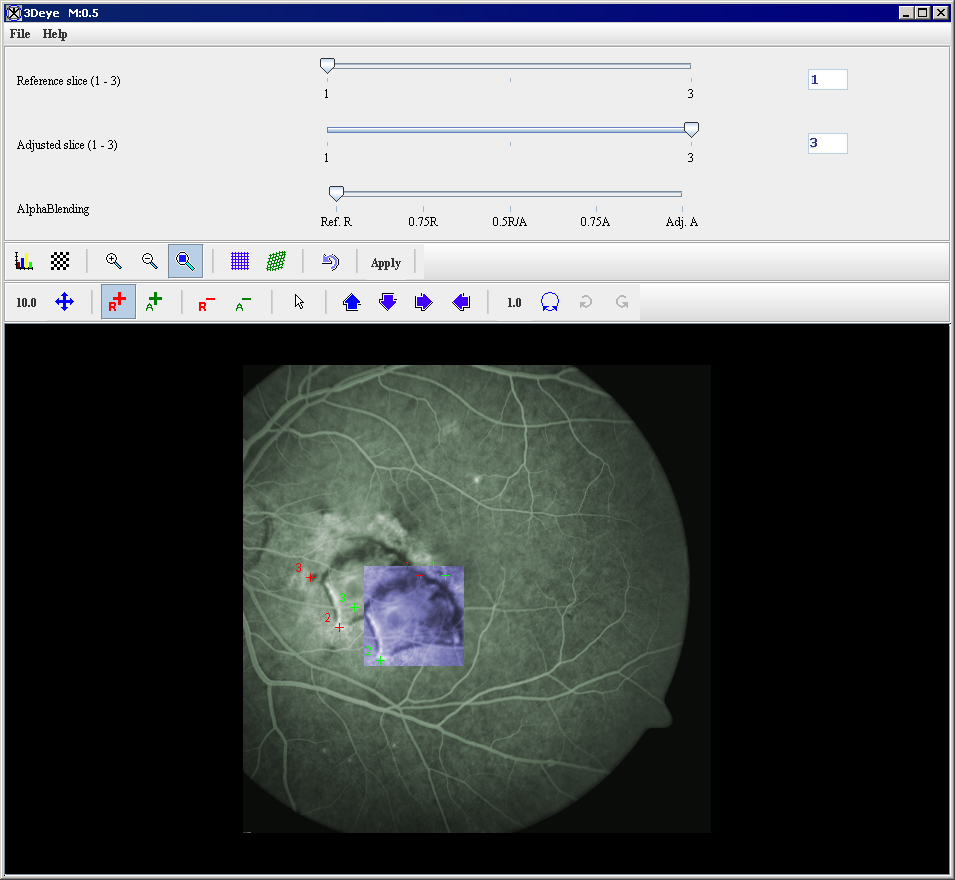
Applying the Manual 2D Series algorithm to 2.5D images
To run this algorithm on 2.5D images, complete the following steps:
- Open a single 2.5 image dataset. When you apply this algorithm, you select the slices in the dataset that you want to register.
- Perform, as an option, any other image processing, except scaling, on the image dataset.
- Select Algorithms > Registration > Manual 2D Series. The Manual 2D Series window for 2.5D images (Figure 12) opens.
- Because you are registering slices of the image, and not separate images, all of the necessary icons and controls appear in a simple window that does not include tabbed pages. Note that two additional sliders appear at the top of the page:
- Reference slice slider allows you to choose which slice to use as a reference image.
- Adjusted slice slider' allows you to choose which slice to use as an image to be registered.
|
|
Note: the boxes to the right of each slider indicate the number of slice which you are currently viewing. All of the remaining icons and controls work in the same way that they do on the Manual 2D Series window for 2D images. |
- Choose the reference and adjusted slice. You can consider using the LUT to distinguish the adjusted image from the reference image as described in Section "Using LUT to arrange the images".
- Use the Alphablending image slider to display only the reference slice and then place at least four landmarks on the reference slice. Repeat the same procedure for the adjusted slice.
- Now, move the image slider arrow all the way to the left on the slider, so the dialog box will display only the reference slice.
- Click the Window Region of Image B icon and position the cursor over the reference image. The Windows Region box appears on the image, filled with the adjusted image, as shown in Figure 12. Use this box to look at alignment of fine detail in the slices.
 |
- At this point, you should determine the following:
- Whether there is a need to make manual adjustments to the registration. If so, use the direction or the rotation icons to verify alignment.
- Whether to run one of the registration algorithms. If so, simply call either the Least Squares or Thin Plate Spline algorithm, as appropriate. Select Apply to keep changes made by the algorithm.
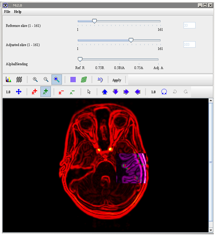
Applying the Manual 2D Series algorithm to 3D images
When you apply this algorithm, you select the slices, which you want to register, in a single 3D dataset. To run the algorithm on 3D images, complete the following steps:
- Open a single3 image dataset. Perform, as an option, any other image processing, except scaling, on the image dataset.
- Select Algorithms > Registration > Manual 2D Series. The Manual 2D Series window for 3D images opens.
- Because you are registering slices of a single 3D image, all of the necessary icons and controls appear in a window that does not include tabs. Note that there are three sliders appear at the top of the page:
- Reference slice slider allows you to choose which slice to use as a reference image.
- Adjusted slice slider' allows you to choose which slice to use as an image to be registered.
- AlphaBlending Slider which, by default, displays both the reference and adjusted slices blended in proportion 50/50.
- Choose the reference and adjusted slice. Use the LUT to differentiate the adjusted image from the reference image. See also: Section [Manual2DSeriesOV.html#wp1866423 "Using LUT to arrange the images" ].
- Use the AlphaBlending image slider to display only the reference slice and then place at least four landmarks on the reference slice. Repeat the same procedure for the adjusted slice.
- Move the image slider arrow all the way to the left on the slider, so the window now displays only the reference slice.
- Click the Window Region of Image B icon and position the cursor over the reference image. The Windows Region box appears on the image, filled with the adjusted image, as shown in Figure 13. You can use either this box or Checker Board to look at alignment of details in the slices.
- At this point, you should figure out the following:
- Whether there is a need to make further manual adjustments to the registration. If so, use the direction or the rotation icons to verify alignment.
- Whether to run one of the registration algorithms. If so, simply call either the Least Squares or Thin Plate Spline algorithm, as appropriate.
- When done, select Apply to keep changes made by the algorithm.
|
|
Note: the boxes to the right of the Reference Slice and Adjusted Slice slider indicate the number of slice which you are currently viewing. All of the remaining icons and controls work in the same way that they do on the Manual 2D Series window for 2D images. |
 |
![]() Translate Image
Translate Image
![]() Rotate Image
Rotate Image
![]() Move up
Move up
![]() Move right
Move right
![]() Apply Least Squares alignment
Apply Least Squares alignment
![]() Apply Thin Plate Spline alignment
Apply Thin Plate Spline alignment
![]() Reference Slice Markers
Reference Slice Markers
![]() Adjusted Slice Markers
Adjusted Slice Markers
![]() Return to Default mode
Return to Default mode
![]() Window region
Window region