Edge detection is possibly the most common method for segmenting objects in medical images. Typically, these algorithms find edges that form a closed contour, which completely bound an object. Currently, MIPAV offers two edge detection algorithms: Zero X Laplacian. and Edge Detection: Zero X Non-Maximum Suppression.
Background
The Laplacian is a 2-D isotropic measure of the 2-nd spatial derivative of an image and can be defined as:
Equation 1
|
|
in 2D images and
Equation 2
|
|
in 3D images.
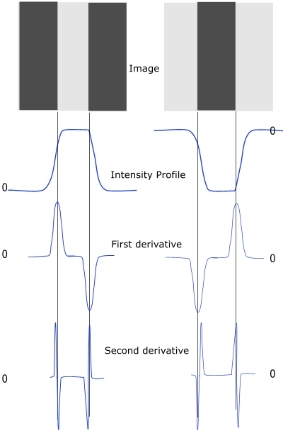
The Laplacian of an image highlights regions of rapid intensity change and therefore can be used for edge detection. Zero X Laplacian algorithm finds edges using the zero-crossing property of the Laplacian. The zero crossing detector looks for places in the Laplacian of an image where the value of the Laplacian passes through zero - i.e. points where the Laplacian changes its sign. Such points often occur at the edges in images - i.e. points where the intensity of the image changes rapidly.
Figure 1 shows that in the approach of a change in intensity, the Laplacian response is positive on the darker side, and negative on the lighter side. This means that at a reasonably sharp edge between two regions of uniform but different intensities, the Laplacian response is:
- zero at a long distance from the edge,
- positive just to one side of the edge,
- negative just to the other side of the edge,
- zero at some point in between, on the edge itself.
 |
However, as a second order derivative, the Laplacian is very sensitive to noise, and thus, to achieve the best result, it should be applied to an image that has been smoothed first. This pre-processing step reduces the high frequency noise components prior to the differentiation step.
The concept of the Zero X Laplacian algorithm is based on convolving the image with 2D Gaussian blur function, first, and then applying the Laplacian. The 2D Gaussian blur function can be defined as
Equation 3
|
|
where ![]() -sigma is a standard deviation. This function blurs the image with the degree of blurring proportional to sigma.
-sigma is a standard deviation. This function blurs the image with the degree of blurring proportional to sigma.
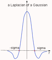
In that case the 2-D Laplacian of the Gaussian (that is the second derivative of h with respect to r) is centered on zero and with Gaussian standard deviation sigma has the form of
Equation 4
|
|
where r2=x2 y2. See also Figure 2.
Since the convolution operation is associative, the method convolves the Gaussian smoothing filter with the Laplacian filter, first, and then convolves this hybrid function (defined by equation 9) with the image to achieve the required result.
 |
Once the image has been Laplacian of a Gaussian filtered, the algorithm detects the zero crossings. Note that, zero crossings might occur at any place where the image intensity gradient starts increasing or starts decreasing, and this may happen at places that are not obviously edges. To cure that problem, the method applies the Marching Squares algorithm to detect those zero crossings that corresponds to edges. To learn more about Marching Squares, refer to Volume 2, Algorithms, "Extract Surface (Marching Cubes)".
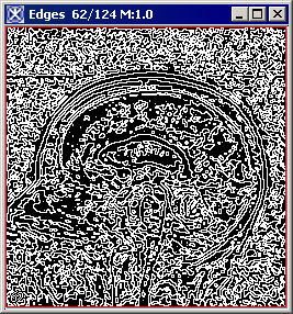
The resulting image is an unsigned byte image with values of 255 at the edges and 0 elsewhere.
Image types
You can apply this algorithm to 2D and 3D grayscale images.
References
See the following references for more information about this algorithm:
http://homepages.inf.ed.ac.uk/rbf/HIPR2/log.htm.
http://homepages.inf.ed.ac.uk/rbf/HIPR2/zeros.htm
Rafael C. Gonzalea, Richard E. Woods, "Digital Image Processing" Second Edition, Prentice Hall, 1992, pp. 581-585.
Applying the Zero X Laplacian algorithm
To run this algorithm, complete the following steps:
- Open an image of interest;
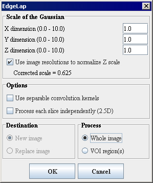
- Select Algorithms > Edge Detection > Zero X Laplacian. The EdgeLap dialog box opens. For the dialog box options, refer to Figure 4.
- Complete the fields in the dialog box. Click OK.
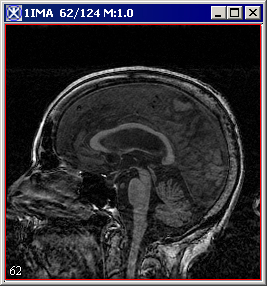
- The algorithm begins to run, and a status window appears. When the algorithm finishes, the resulting image appears as an unsigned byte mask in a new image window as shown in Figure 3.
  |
|
Scale of the Gaussian
|
Specifies the standard deviation of the Gaussian filter in X, Y, and Z directions which were used to determine edges in the image.
|
 |
|
Use image resolutions to normalize Z scale
|
If checked, Z scale*(X resolution/Y resolution) will be used to generate the edge map. If unchecked, Z scale will be used in generation of the edge map.
| |
|
Options
| ||
|
Use separable convolution kernels
|
If checked, the algorithm convolves the image with X kernel and Y kernel independently, and then combines the result images.
| |
|
Process each slice independently (2.5D)
|
Applies the algorithm to each slice individually.
| |
|
Destination
|
New image - this is the default option; Replace image - this option cannot be selected.
| |
|
Process
|
Whole Image - if checked the edge detection will be calculated for the whole image; VOI region - if checked the edge detection will be calculated for the selected VOI.
| |
|
OK
|
Applies the algorithm according to the specifications in this dialog box.
| |
|
Cancel
|
Closes the dialog box.
| |
|
Help
|
Displays online help for this dialog box.
| |